
Adaptive laser system for ophthalmic surgery

a laser system and ophthalmic technology, applied in the field of laser systems, can solve the problems of corneal tears, significant lost opportunity costs, and delay in surgical procedures when the lasers are being fixed, and achieve the effects of reducing the possibility of necrotic tissue formation, reducing the amount of energy per pulse, and reducing the possibility of tears

Active Publication Date: 2018-11-20
BOARD OF TRUSTEES OPERATING MICHIGAN STATE UNIV
View PDF60 Cites 11 Cited by
  • Summary
  • Abstract
  • Description
  • Claims
  • Application Information

AI Technical Summary

Benefits of technology

The present invention provides an adaptive laser system for ophthalmic use that uses a compact and relatively inexpensive laser with a direct diode pumped or Yb-doped gain element, emitting a laser beam pulse with a duration less than 100 fs and output energy less than 2 μJ per pulse. The system also uses non-linear optical (“NLO”) imaging to create three-dimensional mapping of a portion of the eye and automated feedback to assist with a surgical operation. The patient interface uses laser induced markings or indicia to aid in focusing and / or calibration. The system also employs temporal focusing of the laser beam pulse to assist in accurately controlling a depth of cut by a laser beam pulse without harming adjacent tissue. The system should reduce, if not eliminate, undesired bubbles created during ophthalmic surgery, resulting in faster procedures with reduced risk of complications. The specific femtosecond laser configuration of another aspect of the system is considerably less expensive than traditional femtosecond laser devices, making it more accessible for surgical procedures in rural areas and less prosperous countries, and allowing for modularized backup lasers which also avoid down time during shipping and repair of a broken traditional laser.

Problems solved by technology

It is also problematic that bubbles can cause undesired tears in the cornea during surgery.
It is noteworthy, however, that femtosecond lasers employed with conventional ophthalmic systems are extremely expensive and subject to mechanical failure related to the water cooling system, optical including damage to the SESAM saturable absorber, and electronics, if not regularly maintained which leads to significant lost opportunity costs and delays in surgical procedures when the lasers are being fixed.

Method used


Image

  • Adaptive laser system for ophthalmic surgery
  • Adaptive laser system for ophthalmic surgery
  • Adaptive laser system for ophthalmic surgery

Examples


Embodiment Construction

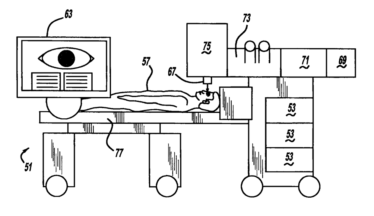
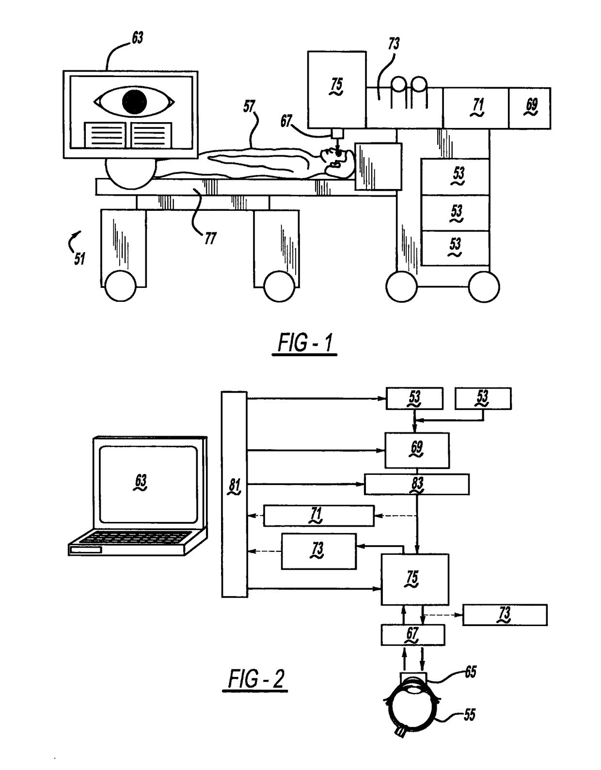
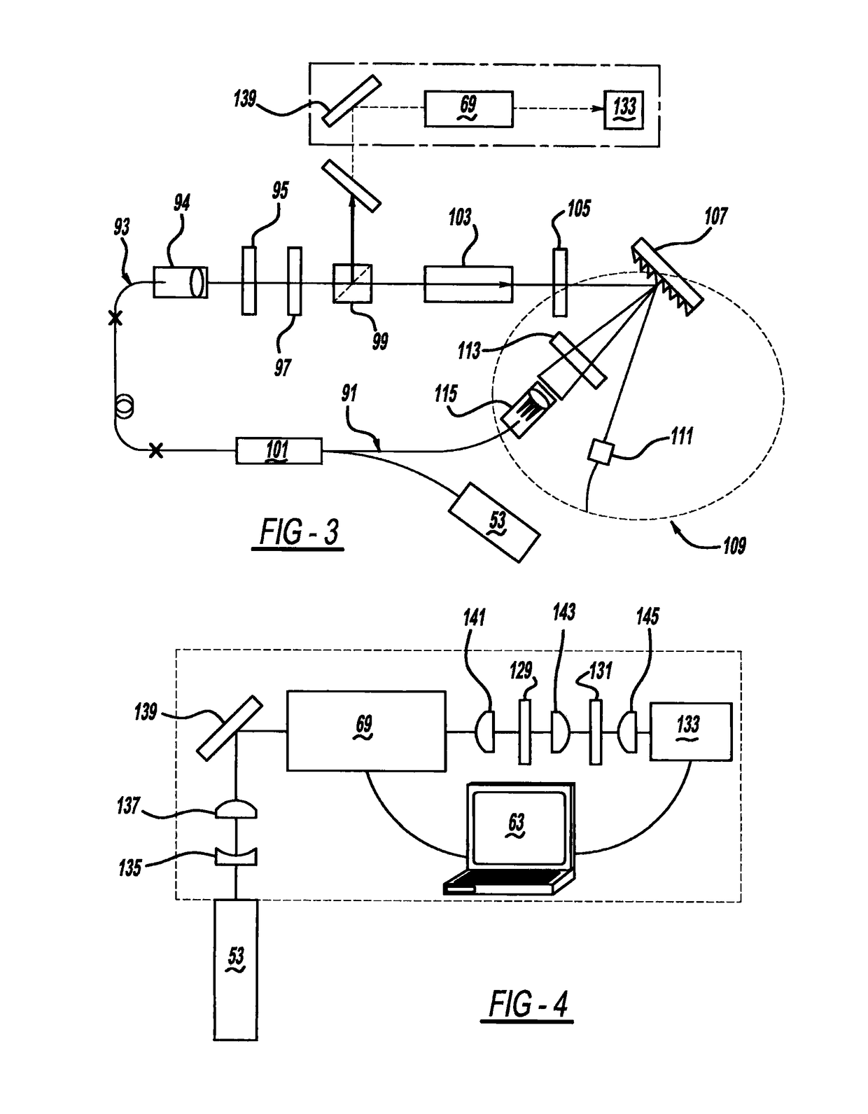
[0053]Referring to FIG. 1-4, the preferred embodiment of an adaptive laser system or machine unit 51 for ophthalmic use of the present invention uses one or more ultrafast lasers 53 to operate on an eye 55 of a patient 57. Each laser 53 is preferably configured with a solid state, unamplified and air cooled diode-pumped Yb gain, in a fiber or hybrid free-space-fiber. The large bandwidth of the preferred laser arises through self-phase modulation within the cavity fiber or through pumping a photonic crystal fiber. This provides a relatively inexpensive laser assembly ideally suited for modularized and interchangeable use. The laser preferably emits a pulse intensity less than 5 μJ and a duration less than 150 fs, more preferably less than 100 fs, and even more preferably less than 50 fs, and for some uses less than 10 fs. The repetition rate is greater than one million pulses per second. This allows faster procedures. Similarly, it is desirable to reduce the energy per pulse to level...


PUM


Abstract

An adaptive laser system for ophthalmic use is provided. In another aspect, a relatively inexpensive laser is employed. In another aspect of the present system, non-linear optical imaging uses multiphoton fluorescences and / or second harmonic generation, to create three-dimensional mapping of a portion of the eye in combination with automated feedback to assist with a surgical operation. In a further aspect of the present system, the patient interface uses laser induced markings or indicia to aid in focusing and / or calibration. Still another aspect employs temporal focusing of the laser beam pulse.

Description

CROSS-REFERENCE TO RELATED APPLICATIONS[0001]This application is a continuation application of PCT International Patent Application Serial No. PCT / US2012 / 030476, filed on Mar. 23, 2012, which claims priority to U.S. Provisional Application Ser. No. 61 / 467,737, filed on Mar. 25, 2011, both of which are incorporated by reference herein.BACKGROUND AND SUMMARY[0002]The present invention relates generally to laser systems and more particularly to an adaptive laser system for ophthalmic use.[0003]It has become common to employ lasers for eye surgery, including cataract surgery, refractive surgery, glaucoma surgery, corneal grafting retinal treatments, keratoplasty, and the like. More recently, ultrafast lasers, having an amplified output of at least 1 μJ per pulse and a duration of at least 250 fs have been used. “Aside from the technical benefits that come along with femtosecond lasers, there were new side effects that arose with the technology that are now better understood. The formati...

Claims


Application Information

Patent Timeline
Patent Type & Authority Patents(United States)
IPC IPC(8): A61B18/20A61F9/008H01S3/00H01S3/16H01S3/11H01S3/067
CPCA61F9/00802A61F9/00831A61F9/00836H01S3/005A61F9/00827H01S3/1675A61F2009/0087A61F2009/00846A61F2009/00863A61F2009/00872G02B2207/114H01S3/0092H01S3/06733H01S3/1112H01S3/1618
Inventor DANTUS, MARCOS
Owner BOARD OF TRUSTEES OPERATING MICHIGAN STATE UNIV
Learn More