
Process for revamping a plant for the production of cyclohexanone

a technology of cyclohexanone and plant, which is applied in the direction of distillation separation, separation machines, chemical industry, etc., can solve the problems of prohibitively expensive replacement or expansion, high cost, etc., and achieve the effect of improving efficiency and increasing the ra

Active Publication Date: 2018-11-20
CAP III
View PDF12 Cites 0 Cited by
  • Summary
  • Abstract
  • Description
  • Claims
  • Application Information

AI Technical Summary

Benefits of technology

The present invention relates to a process for separating cyclohexanone from a mixture of cyclohexanol and cyclohexanone. The process involves oxidizing cyclohexane to produce a mixture of cyclohexanone and cyclohexanol, which is then separated using a distillation process. The invention aims to improve the capacity of the plant for separating cyclohexanone, by increasing the efficiency of the distillation process and reducing the amount of unreacted cyclohexanol and by-products produced per unit weight of cyclohexanone. Additionally, the invention avoids the risk of explosions and the associated safety measures required. The process also allows for the recycling of unreacted phenol and the reuse of residual cyclohexanol, reducing waste and the associated costs. The capacity of the plant is improved by at least 10% compared to a previous plant. The invention also includes a method for recycling cyclohexanol and a process for efficiently dehydrogenating cyclohexanol.

Problems solved by technology

However, there arises a problem when it is desired to increase the capacity of a chemical plant above the maximum of the current design, for example when increased demand of product is experienced.
A major drawback of this approach is the high cost.
However, where such rate-limiting components are complex, it may be prohibitively costly to replace or expand them.

Method used


Image

  • Process for revamping a plant for the production of cyclohexanone
  • Process for revamping a plant for the production of cyclohexanone
  • Process for revamping a plant for the production of cyclohexanone

Examples


example 1

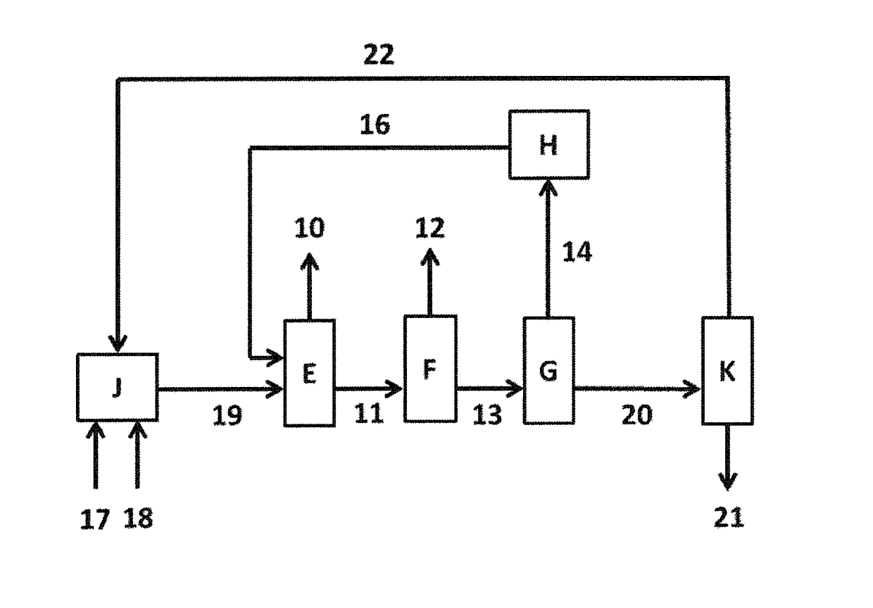
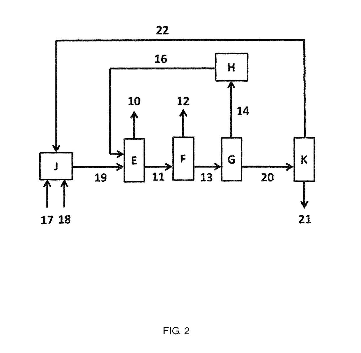
[0125]A chemical plant for the production of cyclohexanone by hydrogenation of phenol, comprising:[0126]a phenol hydrogenation unit;[0127]a lights distillation column;[0128]a cyclohexanone distillation column;[0129]a cyclohexanol distillation column;[0130]a phenol distillation column; and a cyclohexanol dehydrogenation unit;

[0131]as described before and substantially as depicted in FIG. 2 was simulated in Aspen Plus® chemical engineering software with input data obtained from an operating chemical plant as described herein. The simulated plant was designed with an identical cyclohexanone distillation column and an identical cyclohexanol dehydrogenation unit as in Comparative Example A. The cyclohexanone distillation column limited the overall capacity of the plant.

[0132]The hydrogenation of phenol in the phenol hydrogenation unit was performed in the gas phase in the presence of a palladium-comprising catalyst. The resulting gas mixture, comprising phenol, hydrogen gas, cyclohexanol...

example 2

[0141]A chemical plant for the production of cyclohexanone by hydrogenation of phenol, comprising:[0142]a phenol hydrogenation unit;[0143]a lights distillation column;[0144]a cyclohexanone distillation column;[0145]a cyclohexanol distillation column;[0146]a phenol distillation column; and[0147]a cyclohexanol dehydrogenation unit;

[0148]as described before and substantially as depicted in FIG. 2 was simulated in Aspen Plus® chemical engineering software with input data obtained from an operating chemical plant as described herein. The simulated plant was designed with an identical cyclohexanone distillation column and an identical cyclohexanol dehydrogenation unit as in Comparative Example B. The cyclohexanone distillation column limited the overall capacity of the plant.

[0149]The cyclohexanone plant simulated was identical to that of Example 1, except that it included an additional buffer vessel upstream and an additional buffer vessel downstream of the cyclohexanol dehydrogenation u...


PUM

PropertyMeasurementUnit
wt. %aaaaaaaaaa
wt. %aaaaaaaaaa
wt. %aaaaaaaaaa

Abstract

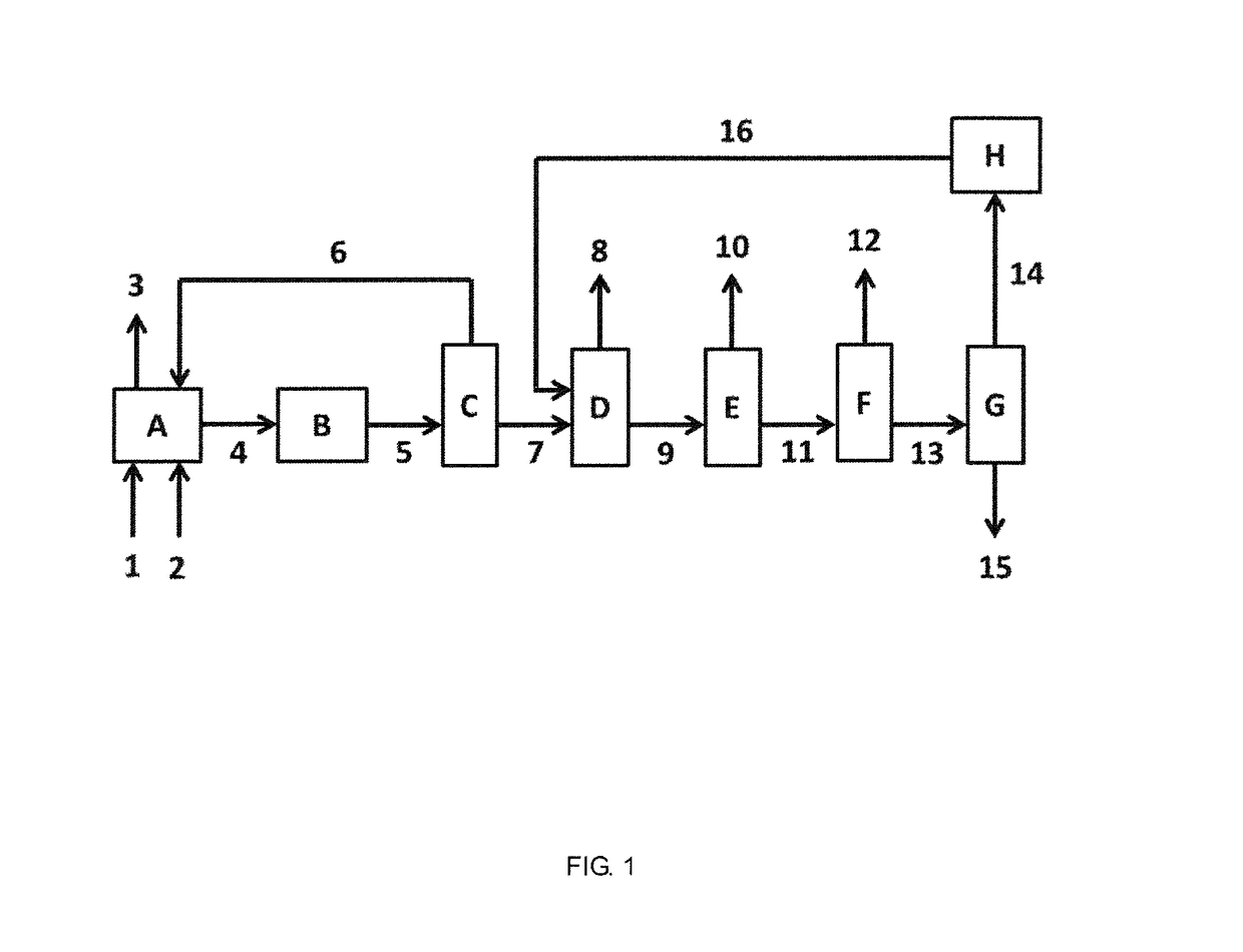
A process for the construction of a second chemical plant, which second chemical plant is suitable for the separation of cyclohexanone from a second mixture, which second mixture comprises reaction products from the hydrogenation of phenol. The process comprises providing a first chemical plant, which first chemical plant is suitable for the separation of cyclohexanone from a first mixture, and a second chemical plant comprising a distillation column suitable for distilling overhead cyclohexanone reused from the first chemical plant.

Description

CROSS-REFERENCE TO RELATED APPLICATIONS[0001]This application is a 35 U.S.C. § 371 national phase filing claiming the benefit of and priority to Patent Cooperation Treaty application no. PCT / EP2015 / 079774, filed Dec. 15, 2015, which claims the benefit of and priority to EP patent application no. 14197946.8, filed on Dec. 15, 2014, the entire contents of the aforementioned disclosures are hereby incorporated by reference herein.STATEMENT REGARDING FEDERALLY SPONSORED RESEARCH OR DEVELOPMENT[0002]Not Applicable.THE NAMES OF THE PARTIES TO A JOINT RESEARCH AGREEMENT[0003]Not Applicable.INCORPORATION-BY-REFERENCE OF MATERIAL SUBMITTED ON A COMPACT DISC OR AS A TEXT FILE VIA THE OFFICE ELECTRONIC FILING SYSTEM (EFS-WEB)[0004]Not Applicable.STATEMENT REGARDING PRIOR DISCLOSURES BY THE INVENTOR OR A JOINT INVENTOR[0005]Not Applicable.BACKGROUND OF THE INVENTION[0006]The present invention relates to a process for constructing a chemical plant for the production of cyclohexanone.[0007]Cycloh...

Claims


Application Information

Patent Timeline
Patent Type & Authority Patents(United States)
IPC IPC(8): B01D3/00B01D3/10B01D3/14C07C27/28C07C35/08C07C45/00C07C49/403C07C45/82B01D3/12
CPCC07C27/28C07C45/006C07C45/82C07C49/403C07C35/08B01D3/009B01D3/10B01D3/12B01D3/143Y02P70/34C07C2601/14C07C45/39Y02P70/10Y02P20/50
Inventor TINGE, JOHAN THOMASVERSCHUREN, IRIS
Owner CAP III
Learn More