Steel for mold, and mold

a mold and steel technology, applied in the field of die steel and mold steel, can solve the problems of reduced mold life, limited application, and prone to severe cracks in the mold, and achieve high high-temperature strength, high heat conduction performance, and high strength

Inactive Publication Date: 2019-01-08
DAIDO STEEL CO LTD
View PDF20 Cites 2 Cited by
  • Summary
  • Abstract
  • Description
  • Claims
  • Application Information

AI Technical Summary

Benefits of technology

[0071]The steel for a mold of the present invention is a low-alloy steel in which none of such elements as Si, Cr, Ni, and Co are added or such elements are added in smaller amounts as compared with conventional high-alloy steels such as maraging steels and precipitation hardening-type stainless steels, to thereby achieve a heightened coefficient of thermal conductivity. Meanwhile, the steel for a mold of the present invention has higher contents of such elements as Mn, Mo, and V as compared with steels for mechanical structural use, to thereby achieve enhanced high-temperature strength. The steel for a mold of the present invention combines high high-temperature strength and a high coefficient of thermal conductivity.
[0072]In addition, the steel for a mold of the present invention remains as a low-alloy steel which as a whole has reduced addition amounts of alloying-elements.
[0081]The mold thus obtained has both high-temperature strength and high heat conduction performance because of the feature of the composition of the steel.
[0082]According to the present invention, it is possible to provide a steel for a mold and a mold, which are capable of attaining both high high-temperature strength and a high coefficient of thermal conductivity.

Problems solved by technology

However, this method has the following drawback.
Due to the reduced distance between the cooling circuit and the molding surface and due to the generation of stronger thermal stress, the mold is prone to develop a severe crack (through crack propagation from the water cooling circuit to the molding surface), which is causative of a decrease in mold life.
Consequently, in cases when the cooling circuit is disposed nearer to the molding surface, there are limitations as a matter of course.
However, with any method in which a mold is produced through machining, it is technically impossible to form a cooling circuit having such a complicated shape.
Although such steels including maraging steels and precipitation hardening-type stainless steels have high-temperature strength sufficient for molds, there is a problem in that these steels have low heat conduction performance (low coefficient of thermal conductivity) since the matrix phase thereof contains elements which are prone to form a solid solution, such as Si, Cr, Ni, and Co, in a large amount.
However, since the material itself has a low coefficient of thermal conductivity, it is difficult to heighten the efficiency of cooling to a sufficient level.
It is a matter of course that in cases where a mold is produced therefrom not by additive manufacturing but by a conventional general production method, the efficiency of cooling (heat exchange) becomes more insufficient.
However, these steels have low high-temperature strength and have a problem in that the molds produced therefrom have a short life.
Namely, there has been no steel provided so far for molds which is capable of giving a mold having sufficient performance in terms of both high-temperature strength and heat conduction performance, regardless of whether or not the mold is manufactured by additive manufacturing.

Method used


Image

  • Steel for mold, and mold
  • Steel for mold, and mold

Examples


examples

[0161]Examples of the present invention are described below in detail.

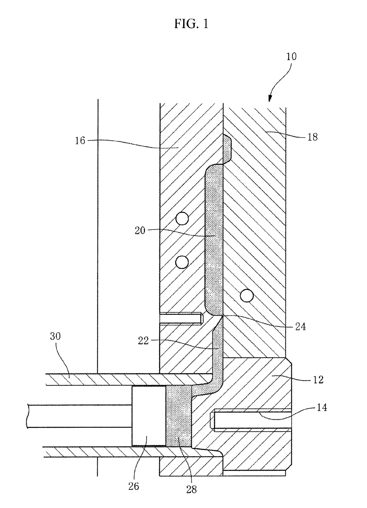
[0162]A powder of each of seventeen types of steels respectively having the chemical compositions shown in Table 1 was produced by a gas atomization method. This powder was used to produce a spool core 12 as a part of the die casting mold 10 illustrated in FIG. 1, by three-dimensional additive manufacturing based on laser irradiation. This spool core 12 has a cooling circuit 14 formed thereinside. This cooling circuit 14 has a three-dimensional, spiral, complicated shape.

[0163]In Table 1, Comparative Example 1 is a die casting steel for hot working SKD61, Comparative Example 2 is an 18Ni maraging steel, Comparative Example 3 is a martensitic stainless steel SUS420J2, and Comparative Example 4 is a steel for mechanical structural use SCM435.

[0164]Although there are cases where each of the Examples according to the present invention contains impurity components in unavoidable amounts, the impurity components are not...


PUM

PropertyMeasurementUnit
coefficient of thermal conductivityaaaaaaaaaa
temperatureaaaaaaaaaa
timeaaaaaaaaaa

Abstract

The present invention relates to a steel for a mold, having a composition containing, on a % by mass basis, 0.25%<C<0.38%, 0.01%<Si<0.30%, 0.92%<Mn<1.80%, 0.8%<Cr<2.2%, 0.8%<Mo<1.4%, and 0.25%<V<0.58%, with the balance being Fe and inevitable impurities, and a mold manufactured by additive manufacturing by using the steel for a mold.

Description

FIELD OF THE INVENTION[0001]The present invention relates to a die steel and a mold steel, and a mold, which are excellent in terms of both high-temperature strength and heat conduction performance.BACKGROUND ART OF THE INVENTION[0002]Molds such as molds for injection molding, molds for die casting, and molds for hot pressing (also called as hot stamping or die quenching), which are used for resins, rubbers, etc., have conventionally been produced generally by melting a steel to form an ingot thereof, thereafter subjecting the ingot to forging and rolling to form a block or a flat rectangular material, machining this material into a shape of a mold, and then giving thereto heat treatments such as quenching and tempering.[0003]A generally employed technique concerning these molds is to form a cooling circuit (water cooling line) within the wall of the mold and pass cooling water therethrough to thereby cool the mold.[0004]In such molds, to heighten the efficiency of cooling with cool...

Claims


Application Information

Patent Timeline
Patent Type & Authority Patents(United States)
IPC IPC(8): B22C9/06C22C38/06C22C38/04C22C38/30B22D17/22B29C45/26B30B15/02B22F5/00C22C33/02C22C38/02C22C38/24C22C38/20B22F3/105C22C38/26C22C38/28C22C38/32C22C38/38C22C38/44C22C38/22C21D1/673B33Y80/00B33Y70/00
CPCB22C9/061B22D17/2209B22F3/1055B22F5/007B29C45/26B30B15/02C22C33/0264C22C38/02C22C38/04C22C38/06C22C38/20C22C38/22C22C38/24C22C38/26C22C38/28C22C38/30C22C38/32C22C38/38C22C38/44Y02P10/295Y02P10/292B22F2999/00B33Y70/00B33Y80/00C21D1/673Y02P10/25B22F10/28
Inventor KAWANO, MASAMICHI
Owner DAIDO STEEL CO LTD
Why Eureka
Try Eureka