Organic EL element comprising first and second interlayers of specified materials and thicknesses, and method for manufacturing thereof

a technology of organic el elements and interlayers, which is applied in the field of organic electroluminescence elements and methods for manufacturing organic el elements, can solve the problems of reduced light emission lifetime, degradation of light emission efficiency, and degradation of storage stability, so as to reduce cathode degradation, maintain excellent light emission properties, and work low

Active Publication Date: 2019-01-15
JOLED INC
View PDF23 Cites 3 Cited by
  • Summary
  • Abstract
  • Description
  • Claims
  • Application Information

AI Technical Summary

Benefits of technology

[0011]The organic EL element pertaining to the one aspect of the present invention includes the first interlayer and the second interlayer. The first interlayer includes a fluorine compound including the first metal that is an alkali metal or an alkaline-earth metal. Accordingly, the first interlayer has a high property of blocking impurities. This blocks intrusion of impurities from the light-emitting layer to suppress degradation of the cathode, and maintains excellent light emission properties. Also, the second metal, which is included in the second interlayer, cleaves the bond between the first metal and fluorine in the fluorine compound including the first metal, which is included in the first interlayer, to liberate the first metal. The liberated first metal is an alkali metal or an alkaline-earth metal, and accordingly has a low work function and a high electron injection property. Therefore, electrons are sufficiently supplied to the light-emitting layer.
[0012]Here, if an amount of the liberated first metal is small, electrons are not sufficiently supplied to the light-emitting layer, and as a result a sufficient luminance is not exhibited. In contrast, if an amount of the liberated first metal is excessively large, an amount of supplied electrons is excessively large relative to an amount of holes in the light-emitting layer. This results in degradation of light emission efficiency (luminance relative to current).
[0013]According to the organic EL element pertaining to one aspect of the present invention, the thickness D1 of the first interlayer and the thickness D2 of the second interlayer satisfy 5%≤D2 / D1≤25%, which represents a preferable range in balancing the property of blocking impurities and the property of supplying electrons, and therefore an excellent light emission efficiency is exhibited.
[0014]Further, according to the organic EL element pertaining to one aspect of the present invention, the sorption layer that includes the third metal, which has the property of taking up and holding impurities (moisture and oxygen), is disposed above the cathode. The sorption layer blocks intrusion of external impurities, thereby suppressing degradation of the cathode, the first interlayer, and the second interlayer, and therefore an excellent storage stability is exhibited.
[0015]Also, according to the method of manufacturing the organic EL element pertaining to another aspect of the present invention, the same effects are exhibited.

Problems solved by technology

This exercises an adverse effect such as degradation of light emission efficiency and reduction of light-emitting lifetime of the organic EL element, and degrades storage stability.
Also, contact between impurities and a cathode causes corrosion and degradation of the cathode.
This can cause the same adverse effects described above.

Method used


Image

  • Organic EL element comprising first and second interlayers of specified materials and thicknesses, and method for manufacturing thereof
  • Organic EL element comprising first and second interlayers of specified materials and thicknesses, and method for manufacturing thereof
  • Organic EL element comprising first and second interlayers of specified materials and thicknesses, and method for manufacturing thereof

Examples


embodiment summary

[Embodiment Summary]

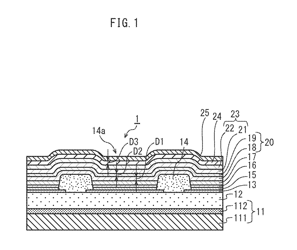
[0163]According to the organic EL element 1 pertaining to the embodiment of the present invention described above, the first interlayer 18 prevents intrusion of impurities from the light-emitting layer 17 into the second interlayer 19 and the cathode thin film layer 21. In addition, the second interlayer 19 promotes electron injection from the cathode 23 to the light-emitting layer 17. This exhibits excellent light emission properties. Furthermore, the sorption layer 24 blocks intrusion of impurities from the sealing layer 25 to the second interlayer 19 and the cathode thin film layer 21, exhibiting excellent light-emitting properties.

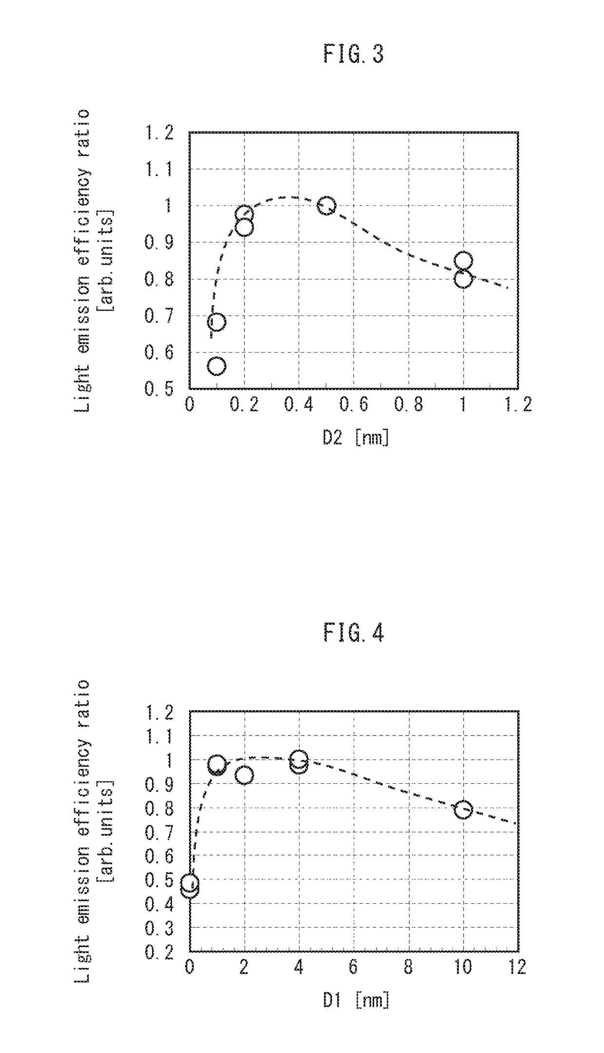
[0164]Further, the thickness D1 of the first interlayer 18 and the thickness D2 of the second interlayer 19 satisfy 5%≤D2 / D1≤25%. This exhibits an excellent light emission efficiency.

[0165]Moreover, since the thickness of the sorption layer 24 is 12 nm or less, a low amount of light absorbed by the sorption layer 24 is achieved and ...

modification 1

(Modification 1)

[0168]According to the above embodiment, the explanation has been given on the example in which the organic EL element 1 includes the cathode auxiliary layer 22. However, this is just an example. The organic EL element 1 may be configured without the cathode auxiliary layer 22. In this case, impurities intruding from the sealing layer 25 are taken up and held by the sorption layer 24, and therefore degradation of the cathode thin film layer 21 by impurities is suppressed more than a case in which the sorption layer 24 is not provided.

[0169]Further, even when the cathode auxiliary layer 22 is not provided, diffusion of the third metal from the sorption layer 24 is suppressed by the cathode thin film layer 21.

modification 2

(Modification 2)

[0170]According to the above embodiment, an explanation has been given on the example in which the organic EL element 1 includes the hole injection layer 15 and the hole transport layer 16. However, this is just an example. Alternatively, the organic EL element 1 need not include at least one or all of these layers.


PUM


Abstract

An organic EL element including an anode; a light-emitting layer above the anode; a first interlayer on the light-emitting layer, the first interlayer including a fluoride of a first metal that is an alkali metal or alkaline earth metal; a second interlayer on the first interlayer, the second interlayer including a second metal that has a property of cleaving a bond between the first metal and fluorine in the fluoride; a cathode on the second interlayer; and a sorption layer above the cathode, the sorption layer including a third metal that has a property of taking up and holding at least one of moisture and oxygen. A thickness D1 of the first interlayer and a thickness D2 of the second interlayer satisfy 5%≤D2 / D1≤25%.

Description

TECHNICAL FIELD[0001]The present invention relates to organic electroluminescence (EL) elements and methods for manufacturing organic EL elements, and in particular to storage stability and light-emitting properties of organic EL elements.BACKGROUND ART[0002]In recent years, display devices employing organic EL elements have become widespread owing to characteristics of the organic EL elements such as a high visibility resulting from self-luminescence and an excellent shock resistance resulting from a fully solid-state structure.[0003]According to a structure of an organic EL element, at least a light-emitting layer is disposed between a pair of electrodes (an anode and a cathode). Further, the organic EL element typically includes, between the light-emitting layer and the cathode, a functional layer (an electron transport layer, an electron injection layer) for supplying electrons to the light-emitting layer, a hole injection layer, a hole transport layer, and so on. Also, it is kn...

Claims


Application Information

Patent Timeline
Patent Type & Authority Patents(United States)
IPC IPC(8): H01L51/52H01L51/54H01L51/50H01L51/56H01L27/32
CPCH01L51/5259H01L51/5092H01L51/5228H01L51/5234H01L51/5262H01L51/56H01L2251/558H01L27/3246H01L51/5237H01L51/5253H01L2227/323H01L2251/301H10K50/171H10K50/828H10K50/846H10K50/85H10K2102/351H10K50/824H10K71/00H10K50/84H10K50/844H10K59/122H10K59/1201H10K2102/00
Inventor MATSUSUE, NORIYUKIKATAGIRI, HIROSHI
Owner JOLED INC
Why Eureka
Try Eureka