Integrated multi-position force lubrication system

a multi-position force lubrication and integrated technology, applied in mechanical actuated clutches, braking systems, couplings, etc., can solve the problems of inability to properly drain the oil to a wet sump, add significant hardware expense, and significant expense to the installation of pto, etc., to save space, reduce installation cost, and easily rota

Active Publication Date: 2019-03-12
TWIN DISC
View PDF22 Cites 5 Cited by
  • Summary
  • Abstract
  • Description
  • Claims
  • Application Information

AI Technical Summary

Benefits of technology

[0011]The inventive PTO has a modular design allowing suitability for both side-load “P” and in-line “I” applications with the simple change of bearing carriers. An advanced control system, allowing for smooth engagement of the driven equipment, may also be utilized. Another feature is a pair of auxiliary drive pump pads with approximately 400 hp maximum capacity per tower, or about 550 hp maximum for both towers. The pump towers are rotatable by approximately 0°, 45°, and 90°, either clockwise or counter-clockwise, to allow for clearance in installation.
[0021]In order to facilitate the indexing of the tower housing with respect to the clutch housing, a multi-position adapter is arranged between the tower and clutch housings. The multi-position adapter includes spaced-apart openings that align with various passages of the hydraulic and tower housings. When selecting an angularly indexed position to mount the tower housing with respect to the clutch housing, the multi-position adapter defines corresponding oil flow paths between respective ones of the passages of the hydraulic and tower housing and blocks flow through the remainder of the passages of the hydraulic and tower housings. This allows for the PTO to operate with a gravity drained hydraulic oil system with a common sump at the lowest point of the clutch housing, despite the indexed orientation of the adjustable tower housing.

Problems solved by technology

Different applications require different tower orientations relative to the main PTO housings, which can present challenges for the oil flow path routing for shared lubrication of the tower sections and main PTO housings.
Accordingly, gravity could not be relied on to properly drain the oil to a wet sump, since each installation of the PTO most often requires a unique orientation.
Oil plumbing kits or adding supplemental hydraulic lines, pumps, and reservoirs to the PTO adds significant expense to the hardware as well as significant expense to the installation of the PTO.

Method used


Image

  • Integrated multi-position force lubrication system
  • Integrated multi-position force lubrication system
  • Integrated multi-position force lubrication system

Examples


Embodiment Construction

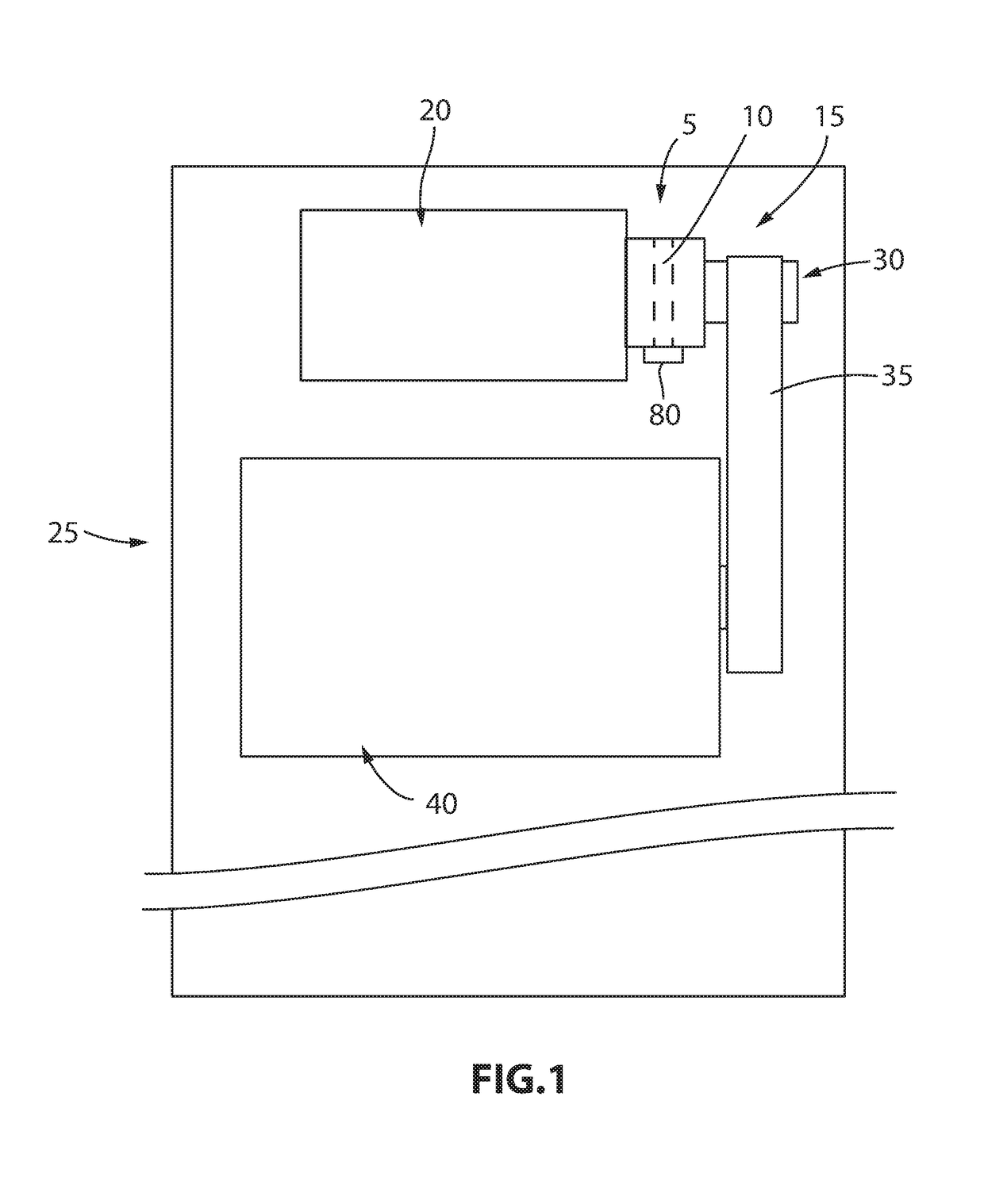
[0036]Referring now to the simplified schematic representation in FIG. 1, a hydraulic PTO (power take-off) 5 with a multi-position forced lubrication system 10 and including a sump 80 is shown implemented in an industrial drive 15. The industrial drive 15 delivers power from a prime mover 20, which may be a high-power internal combustion engine, to a piece of industrial equipment 25. Industrial drive 15 is shown here configured for side-load power delivery and includes a pulley arrangement 30 and belt(s) 35 that transmit power from hydraulic PTO 5 to a driven component(s) of the industrial equipment 25. The drive need not be limited to a pulley arrangement 30 and belt(s) 35 as shown, but may be any known drive such as direct drive, chain drive, or the like.

[0037]The industrial equipment 25 may be, for example, a whole-tree chipper or other industrial wood chipper, a heavy-duty pump system, a grinder, a crusher, a dredge, a shredder, or a heavy-duty drill system that has a large rota...


PUM


Abstract

A hydraulic power take-off, PTO, is provided for use with industrial drives. The hydraulic power take-off has a multi-position adapter that allows the PTO to be attached to a prime mover in a multitude of angularly indexed positions while maintaining a gravity-assisted drain and sump for the hydraulic fluid. The multi-position adapter is indexable to selectively block and allow for passage of oil from a tower housing to a clutch housing thus ensuring the hydraulic oil properly drains. As a result, the tower housing is also indexable which allows the PTO unit to be installed in a number of different configurations to meet the demands of the prime mover and the final application of the industrial machine.

Description

CROSS REFERENCE TO RELATED APPLICATIONS[0001]This application claims the benefit of priority under 35 USC § 119(e) to U.S. Provisional Patent Application No. 62 / 296,978, filed Feb. 18, 2016, the entire contents of which are hereby expressly incorporated by reference into the present application.BACKGROUND OF THE INVENTION[0002]Field of the Invention[0003]The preferred embodiments are directed to an industrial hydraulic power take-off unit (PTO) and more particularly, to a hydraulic PTO which does not require a clutch adjustment and which allows for maximum side load capability. The invention can be used wherever a disconnect is required between the driven equipment and the prime mover. The inventive PTO may be used in any stationary or mobile applications such as within the wood chipping industry where wood chippers are configured to chip whole trees of a large diameter, or perhaps on an agricultural tractor, dump truck, boom, winch, or the like.[0004]Discussion of the Related Art[0...

Claims


Application Information

Patent Timeline
Patent Type & Authority Patents(United States)
IPC IPC(8): B60K17/02F16D13/52F16D67/04B60K17/28B60K25/00F16D25/12B60T1/06B60K25/02
CPCF16D25/123B60K17/02B60K17/28B60K25/00B60T1/062F16D67/04F16D13/52F16D2300/26B60K25/02B60K2025/022B60K2025/026F16D2300/06
Inventor JONES, DARREL A.VAN HOORN, ANDREW D.
Owner TWIN DISC
Why Eureka
Try Eureka