Eureka AIR delivers breakthrough ideas for toughest innovation challenges, trusted by R&D personnel around the world.

Device and method for multispot scanning microscopy

a multi-spot scanning and microscopy technology, applied in the field of multi-spot scanning microscopy devices, can solve the problems of affecting the image quality of the image, the method continues to have a series of problems, and the image recording is relatively slow, so as to reduce the damage of the photo, avoid spectral cross-excitation, and increase the scanning speed

Active Publication Date: 2019-06-04
CARL ZEISS MICROSCOPY GMBH
View PDF22 Cites 1 Cited by
  • Summary
  • Abstract
  • Description
  • Claims
  • Application Information

AI Technical Summary

Benefits of technology

[0021]An essential advantage of the present invention can be seen in that the device according to the invention can be optimised in dependence upon the specimen or can even optimise itself such that a significant increase in the scanning speed, a reduction in the photo damage, avoidance of spectral cross-excitations or an increase in the signal-to-noise ratio can be achieved. Furthermore in different excitation / detection paths thus formed, different types of sensors can be combined (for example the combination of a spatially resolving, for example pixelated, detector, with which the point spread function (PSF) can be spatially measured, with an integrating detector). A flexible optical arrangement for different measurement tasks in biomedical imaging is thus provided. At the same time a new spectrally selective microscopy method is provided.
[0022]The first optical means and the second optical means preferably have as common components at least one microscope objective, an x-y scanner unit and / or at least one main colour splitter.
[0023]The essential advantages of the invention are already realised by the spectrum of the illumination light being set separately and independently in a plurality of illumination sub-beams. It is particularly preferred, however, for a controllable spectral selection means to be present additionally in the device according to the invention in the detection optical path for at least two of the detection sub-beams to independently influence a spectral composition of detection light passing via the respective detection sub-beam to the detection unit, and the control and evaluation unit is also designed to control the spectral selection means. A variant of the method according to the invention corresponds thereto, wherein in the case of at least two detection sub-beams a spectral composition of detection light passing via the respective detection sub-beam onto the detection unit is independently influenced. In these variants the particular advantage is achieved that both on the illumination side and also on the detection side there is a spectral selection. The measurement can therefore be tailored highly specifically to the respective specimen and in particular to the fluorescence dyes respectively used.
[0024]In principle the essential idea of the invention is already realised if the spectral composition can be independently set in at least two illumination sub-beams. However, variants of the device according to the invention are particularly preferred, wherein a beam manipulation means is present in the illumination optical path for each illumination sub-beam for independent setting or adjustment of a spectral composition of the respective illumination sub-beam. A variant of the method according to the invention, wherein the spectral composition of the illumination light is set independently for each illumination sub-beam, corresponds to these exemplary embodiments. The above-described advantages according to the invention that the illumination and detection can be particularly well adapted to specimens in principle of any kind and in principle any desired fluorescence dyes are thereby achieved in a particular way. In particular it is possible to also measure spectrally overlapping bands with the device according to the invention.
[0025]For the same reason, exemplary embodiments of the device according to the invention are preferred, wherein a controllable spectral selection means is present in the detection optical path for each detection sub-beam for independent influencing of a spectral composition of detection light passing via the respective detection sub-beam to the detection unit. In a variant of the method according to the invention, in each detection sub-beam the spectral composition of detection light passing via the respective detection sub-beam to the detection unit is independently influenced accordingly. A highly functional device as well as a method that can be comprehensively configured with respect to the most varied measurement situations are provided with these exemplary embodiments.
[0026]In principle, for example if multiplexing technologies are used, a single detector can be sufficient to detect the detection light. However, the detection unit preferably has a plurality of individual detectors for measuring the detection light emitted respectively by a certain light spot on the specimen. The measurement data can then be particularly effectively recorded.

Problems solved by technology

However, the method continues to have a series of problems.
These include firstly a significant tendency for bleaching of the fluorescence and generally for photo damage to the specimen, secondly a relatively slow image recording and thirdly increased noise in comparison with wide field methods.
On the other hand the scanning of the specimen facilitates only a slow image formation which is limited by the speed of the scanners or by the emission rate of the dyes in the specimen.
Irrespectively of its very wide dissemination in the life sciences, confocal microscopy has in particular the problem that for signal generation with an acceptable signal-to-noise ratio (SNR) a certain number of photons must be generated in a short time (e.g. 10 MHz rate signal photons for detection of 10 photons in a pixel time of 1 μs with a SNR of approximately 3; the rate in the specimen must still be significantly higher due to the losses in the system).
This is associated firstly with the bleaching of the specimen and secondly with damage that makes the examination of many parameters in the field of living cell microscopy impossible or at least considerably more difficult.
The inherent dilemma in relation to the three basic requirements: 1) image speed, 2) good signal-to-noise ratio and 3) low photo damage cannot therefore be resolved with the single spot laser scanning microscope.
The scanning of the specimen with only one laser focus is also disadvantageous in relation to this point.
However, even in the case of a spectrally selective detection, so called cross-excitations always arise and detection of undesired spectral portions which can lead to a false assignment of structures or an undesired background.
However, these systems cannot be used flexibly.
In addition the detection is limited to cameras, which makes a detection of more than 2 spectral channels considerably more difficult.
In addition it is not possible to electronically zoom into the specimen with these non-scanner-based systems.
Point measurements, such as fluorescence correlation spectroscopy, are not possible at all with these systems.
Further multipoint systems have been described in DE 102 15 162 B4, WO 13 131 808 A1, U.S. Pat. No. 6,028,306 A. A problem with these systems always arises in the provision of the scanning laser points.
In AT-131942-E, different lasers are used for different scanning points, which greatly limits the flexibility of this system.
Furthermore the brightnesses of individual beams and colours cannot be individually tuned, which constitutes a problem when structures with a differing level of marking with different dyes are to be examined.
However, the colour channels are thereby fixedly predefined and not configurable.
This system cannot therefore be optimised, in the case of specimens that contain fewer than the number of dyes that can be detected in principle, with respect to other parameters such as for example specimen preservation or speed, as the wavelength distribution is fixedly predefined.

Method used


Image

  • Device and method for multispot scanning microscopy
  • Device and method for multispot scanning microscopy
  • Device and method for multispot scanning microscopy

Examples


Embodiment Construction

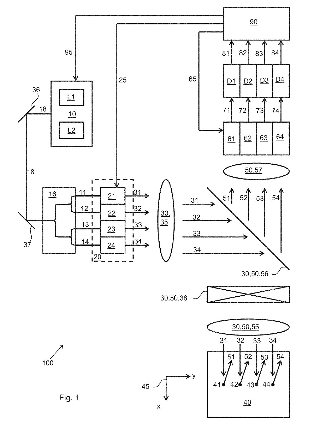
[0062]The basic principle for the measurement with the device according to the invention is based on a laser scanning microscope. The optical arrangement of the microscope is designed so that operation in a parallel mode is optically produced. It is crucial that a plurality of illumination light beams can be coupled into the microscope.

[0063]A certain number of laser lines can be offered to this microscope for spectral illumination. Firstly it is irrelevant whether they are discrete laser lines, a tunable laser or a white light laser. In addition it is insignificant whether the lasers are continuous or pulsed. Finally the usability of the invention is not limited to certain excitation mechanisms such as for example the usual fluorescence excitation. Non-linear processes, in particular two-photon processes, such as in two-photon fluorescence or CARS microscopy, can be used. These spectral components can be mirrored, in particular using a main colour splitter, into the optical path of...


PUM

PropertyMeasurementUnit
resonance frequenciesaaaaaaaaaa
multispot scanning microscopyaaaaaaaaaa
spectral compositionaaaaaaaaaa

Abstract

The invention relates to a device for multispot scanning microscopy, having a multicolor light source for providing at least one illumination light beam, having a splitting device for splitting the illumination light beam into a plurality of illumination sub-beams, having first optical means for providing an illumination optical path for guiding and focusing the individual illumination sub-beams respectively into a light spot on or in a specimen to be examined, having a scan unit for guiding the light spots over the probe, having a detection unit for detecting detection light emitted by the specimen in detection sub-beams after irradiation with the individual illumination sub-beams, having second optical means for providing a detection optical path for guiding the detection sub-beams to the detector unit, having a control and evaluation unit for controlling the scan unit and for evaluating the detection light detected by the detection unit. The device is characterized in that in the illumination optical path for at least two of the illumination sub-beams a controllable beam manipulation means is present for independent setting of a spectral composition of the respective illumination sub-beam, and the control and evaluation unit is designed to control the beam manipulation means. The invention further relates to a method for multispot scanning microscopy.

Description

REFERENCE TO RELATED APPLICATIONS[0001]The current application claims priority to German Application No. 10 2016 102 286.1, which was filed on 10 Feb. 2016, and which is hereby incorporated by reference.TECHNICAL FIELD[0002]The present invention relates in a first aspect to a device for multispot scanning microscopy according to the preamble of claim 1. In a second aspect the invention relates to a method for multispot scanning microscopy according to the preamble of claim 24.BACKGROUND[0003]A generic device for multispot scanning microscopy is described for example in WO-13 131 808 A1 and has the following components: a multicolour light source for providing at least one illumination light beam, a splitting device for splitting the illumination light beam into a plurality of illumination sub-beams, first optical means for providing an illumination optical path to guide and focus the individual illumination sub-beams respectively into a light spot on or in a specimen to be examined,...

Claims


Application Information

Patent Timeline
Patent Type & Authority Patents(United States)
IPC IPC(8): G02B21/00G02F1/11
CPCG02B21/0064G02B21/008G02F1/116G02B21/0076G02F1/113G02B21/0032G01N21/6458
Inventor ANHUT, TIEMOSCHWEDT, DANIELKAUFHOLD, TOBIASROSCHER, BURKHARDWILHELM, STEFAN
Owner CARL ZEISS MICROSCOPY GMBH
Why Eureka
Eureka Blog
Learn More