Hydrocarbon salinity measurement system at bottom of well at extreme conditions of pressure and temperature by means of time domain reflectometry

a technology of salinity measurement and oil well, which is applied in the direction of measurement devices, instruments, material resistance, etc., can solve the problems of high cost of oil, difficult detection of inability to detect capacity isolated devices or inductive faults

Active Publication Date: 2020-02-04
INST MEXICANO DEL GASOLINEEO
View PDF10 Cites 0 Cited by
  • Summary
  • Abstract
  • Description
  • Claims
  • Application Information

AI Technical Summary

Benefits of technology

[0024]The patent US20040100273A1, entitled “Testing Electrical Integrity of Electrically Heated Subsea Pipelines”, refers to a method where electrical connectivity is tested by Time Domain Reflectometry (TDR) of a heating system of the pipes coming from the Wells and cross the seabed to the surface. This heating of the pipes is required to prevent thermal shocks or cooling of the oil as it passes through the seabed.

Problems solved by technology

TDR analysis generally does not detect capacity isolated devices or inductive.
If the fault is very small, the energy of a small pulse may not be enough to travel through the wire, see the fault and that the reflected pulse travel back, this added to the attenuation of the wire, can cause the detection of this fault becomes a bit difficult.
In addition to the need to incorporate reserves, there is the cost of high oil prices, which motivate the application of new technologies for improved recovery of hydrocarbons.
However, because of the accuracy required to quantify the TDR return signal, this technology has not been commercially applied under standard conditions to ambient temperature and pressure, much less to downhole conditions.

Method used


Image

  • Hydrocarbon salinity measurement system at bottom of well at extreme conditions of pressure and temperature by means of time domain reflectometry
  • Hydrocarbon salinity measurement system at bottom of well at extreme conditions of pressure and temperature by means of time domain reflectometry
  • Hydrocarbon salinity measurement system at bottom of well at extreme conditions of pressure and temperature by means of time domain reflectometry

Examples


Embodiment Construction

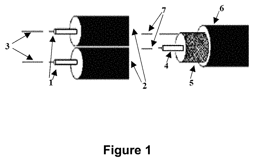
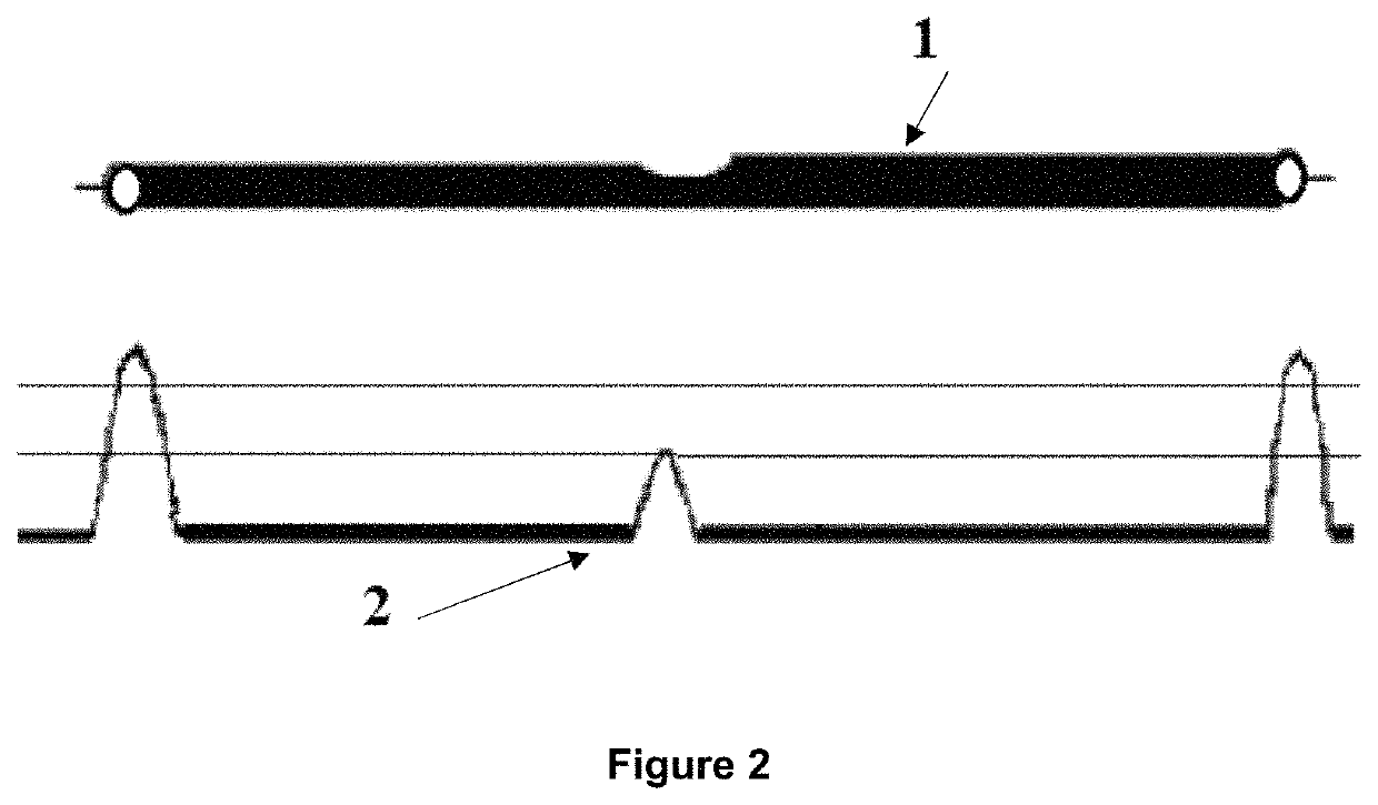
[0036]The system for measuring salinity in wellbore hydrocarbons using the time domain reflectometry (TDR) technique is based on a pulse generator that sends a pulse through a waveguide or cable, This metal waveguide is brought into contact with the hydrocarbon at which its salinity is to be measured, the return signal is measured on an oscilloscope where it is compared to the originally sent pulse. The time of arrival and amplitude of the return pulse are reflections of the change in impedance change at several points or at the end of the line, these changes in the impedance can be measured and analyzed. Given a velocity of propagation of the pulse in the line, the arrival time of the return pulse depends on the location of the impedance change, whereas the amplitude of the return pulse is related to the attenuation of the signal in the cable due to the Length of said cable.

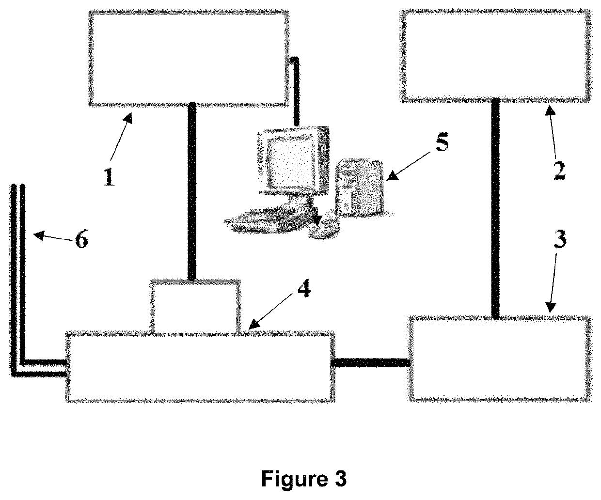
[0037]How to mentioned above, FIG. 4 shows how the waveguide (1) (2) would be installed inside an oil well (3...


PUM

PropertyMeasurementUnit
pressuresaaaaaaaaaa
temperaturesaaaaaaaaaa
lengthsaaaaaaaaaa

Abstract

The object of the present invention relates to a system for measuring the salinity of hydrocarbons at the bottom of an oil well, using the technique of time domain reflectometry (TDR). The system comprises an electromagnetic pulse generator, an oscilloscope for displaying and measuring the frequency, amplitude and wavelength of the signal, a signal amplifier, a computer for processing and storing the information, and a metal wire that functions as a waveguide To transmit the signal from the signal generator to the hydrocarbon to which its salinity is to be determined at the bottom of the well. The signal returns from the bottom of the well to the oscilloscope where the difference between the sent signal and the return signal is measured. This difference allows us to infer the salinity of the hydrocarbon. The guide wire is attached to the production line by means of a strap or other fastening device from the surface to the bottom of the well, where the tip of the cable is inserted into the pipe to contact the hydrocarbon and in this way detect its salinity. It is possible to use the same pipe as a waveguide to transmit the test signal to the bottom of the well. In addition, the salinity of the hydrocarbon can be determined at different points along the well.

Description

TECHNICAL FIELD OF THE INVENTION[0001]The present invention relates to a salinity measuring system at the bottom of an oil well, using the time domain reflectometry (TDR) technique. The system comprises an electromagnetic pulse generator, an oscilloscope for displaying and measuring the frequency, amplitude and wavelength of the signal, a signal amplifier, a computer to process and store information and a metal cable that functions as a waveguide to transmit the signal from the signal generator to the hydrocarbon to which its salinity at the bottom of the well is to be determined. The signal returns from the bottom of the well to the oscilloscope where the difference between the sent signal and the return signal is measured. This difference allows us to infer the salinity of the hydrocarbon. The guide wire is attached to the production line by means of a strap or some other fastening device from the surface to the bottom of the well, where the tip of the cable is introduced to the p...

Claims


Application Information

Patent Timeline
Patent Type & Authority Patents(United States)
IPC IPC(8): G01N27/06G01N33/28
CPCG01N33/2835G01N27/06G01N27/028
Inventor ORDUNA REYES, ERNESTODOMINGUEZ ESQUIVEL, JOSE MANUELGARCIA Y GARCIA, JOSE
Owner INST MEXICANO DEL GASOLINEEO
Why Eureka
Try Eureka