Bandgap reference circuit and high-order temperature compensation method

a reference circuit and high-order temperature compensation technology, applied in the field of circuit technologies, can solve the problems of increasing the risk of process mismatch, increasing the power consumption of modules, and the inability to manufacture modules using conventional processes, etc., to achieve simple and efficient, improve the accuracy and improve the effect of bandgap reference sources

Active Publication Date: 2020-03-24
PURESEMI CO LTD
View PDF14 Cites 3 Cited by
  • Summary
  • Abstract
  • Description
  • Claims
  • Application Information

AI Technical Summary

Benefits of technology

[0028]Compared with the prior art, the present invention has the following advantages:
[0029]The present invention is a simple and efficient compensation circuit for improving the accuracy of a bandgap reference source. The compensation method of the circuit is to perform curvature correction by using a sub-threshold current of a CMOS transistor, where a temperature coefficient thereof can reach 6 ppm / ° C. The circuit is simple in structure, does not increase the power consumption of a module or increase the requirements for a power voltage, and can be implemented in any CMOS process. A manner not increasing circuit complexity can be adopted for implementation, the accuracy of a bandgap reference source can be greatly improved, and power consumption, chip area and cost are reduced.

Problems solved by technology

However, a common high-order temperature compensation scheme has the following problems: 1) a compensation circuit is excessively complicated, and this increases the risk of process mismatch and increases the power consumption of a module; 2) a specific process is required, and this module cannot be manufactured by using a conventional process.
However, this circuit implements a first-order bandgap reference voltage through a MOS transistor, and a complicated circuit is used to implement high-order temperature compensation.
The present invention generates a bandgap reference through a conventional triode structure, and uses a sub-threshold current of an NMOS transistor to implement high-order compensation, which is excessively complicated, increases the risk of process mismatch, and increases the power consumption, cost and reject rate of modules.

Method used


Image

  • Bandgap reference circuit and high-order temperature compensation method
  • Bandgap reference circuit and high-order temperature compensation method
  • Bandgap reference circuit and high-order temperature compensation method

Examples


embodiment 1

[0037]The present invention will now be described in detail with reference to the drawings.

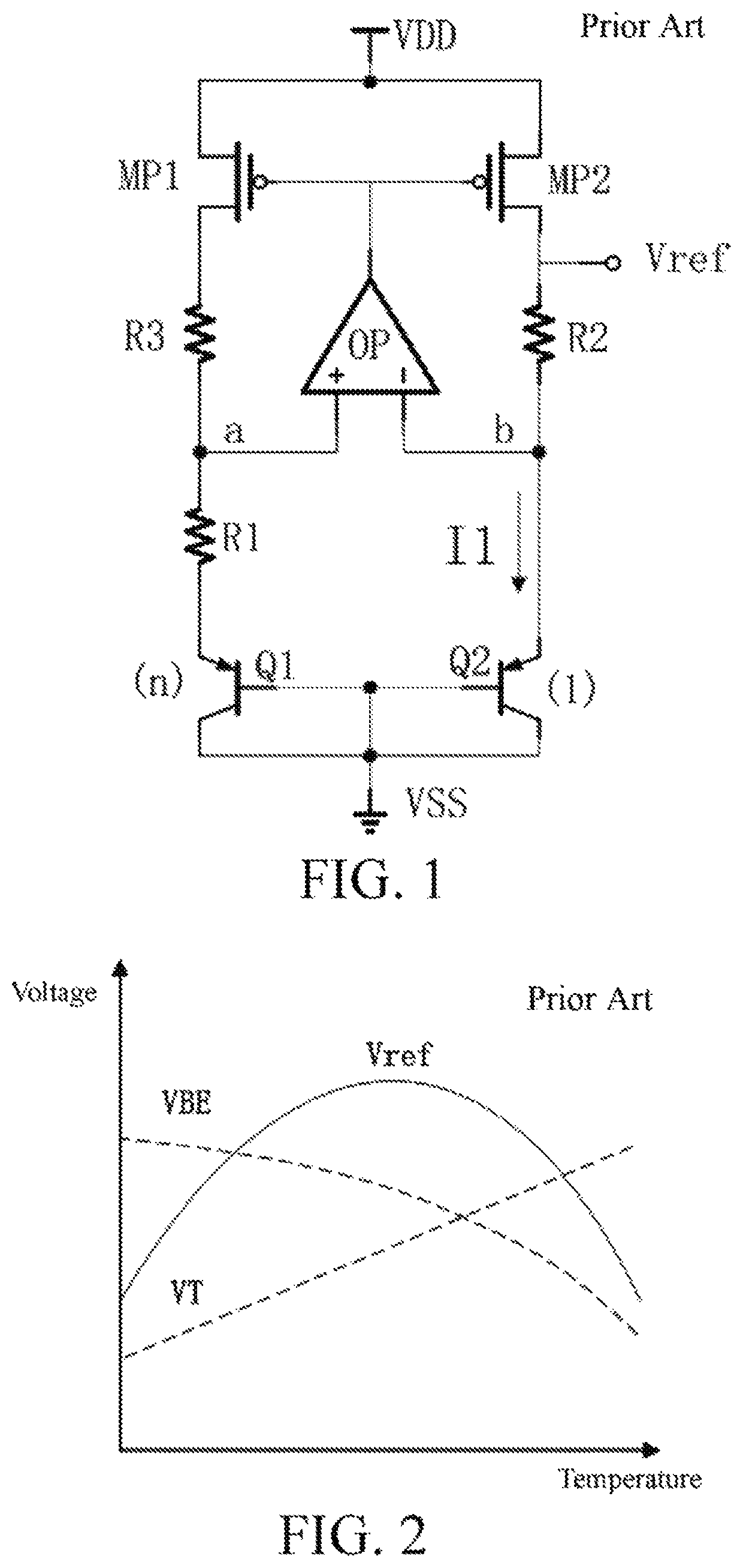
[0038]Since a bandgap reference varies with temperature due to several non-ideal effects: a temperature coefficient of a resistor, a gain of a clamping operational amplifier, a parasitic current, channel length modulation, and the nonlinearity of a VBE temperature coefficient. Among these factors, the nonlinearity of the VBE temperature coefficient is the main reason. The formula for VBE variation with temperature is:

[0039]VB⁡(T)=Vg⁢⁢0-TTH·[Vg⁢⁢0-VB⁡(TR)]-(η-α)·VT·I⁢⁢1⁢(TTH)(3)

[0040]where Vg0 is the voltage between base and emitter when temperature is 0 K, TR is room temperature, η is a process-dependent constant, independent of temperature, ranging from 3 to 3.5, and α is an index of a collector current temperature T.

[0041]The second item on the right of equation in Formula (3) is a first-order function of temperature, which can be canceled by a thermal voltage VT with a positive temperature ...


PUM

PropertyMeasurementUnit
drain-source voltageaaaaaaaaaa
voltagesaaaaaaaaaa
temperature coefficientaaaaaaaaaa

Abstract

A bandgap reference circuit and a high-order temperature compensation method are disclosed. The bandgap reference circuit includes: a starting circuit, a bias circuit and a high-order compensated bandgap reference voltage generating circuit, where a compensation method of the high-order compensated bandgap reference voltage generating circuit is to perform curvature correction by using a sub-threshold current of a CMOS transistor to obtain a high-order temperature-compensated bandgap reference voltage source circuit. The present circuit has the advantages that a manner not increasing circuit complexity can be adopted for implementation, the accuracy of a bandgap reference source can be greatly improved, and power consumption, chip area and cost are reduced.

Description

BACKGROUNDTechnical Field[0001]The present invention relates to the field of circuit technologies, and in particular, to a bandgap reference circuit and a high-order temperature compensation method.Related Art[0002]In the prior art, a bandgap reference circuit is an essential circuit module that is indispensable in an analog integrated circuit. It is widely used in LED drive circuits, switching power converters, digital to analog converters, analog to digital converters, and linear voltage regulators.[0003]FIG. 1 shows a conventional bandgap reference voltage source having a working principle as follows: balancing by the summation of two voltages with opposite temperature coefficients: VBE with a negative temperature coefficient and a thermal voltage VT with a positive temperature coefficient. The thermal voltage is given by kT / q, where k is a Boltzmann constant, T is a temperature, and q is an electron charge. A high-gain operational amplifier has the same voltage at an operational...

Claims


Application Information

Patent Timeline
Patent Type & Authority Patents(United States)
IPC IPC(8): G05F3/26
CPCG05F3/262G05F3/30Y02B70/10
Inventor HE, SHUZHUANJIANG, ZHAOYUCHEN, JUNJIE
Owner PURESEMI CO LTD
Why Eureka
Try Eureka