Method and system for capturing high-purity CO2 in a hydrocarbon facility

a technology of high-purity co2 and hydrocarbon facilities, which is applied in the direction of fusion electrolyte fuel cells, sustainable manufacturing/processing, and separation processes, etc., can solve the problems of environmental undesirable, inefficient and wasteful each process of utilizing co2 and simply venting co2 into the atmosphere, etc., to achieve high purity and reduce co2 emissions

Active Publication Date: 2020-04-14
SAUDI ARABIAN OIL CO
View PDF9 Cites 2 Cited by
  • Summary
  • Abstract
  • Description
  • Claims
  • Application Information

AI Technical Summary

Benefits of technology

[0004]Embodiments of the present disclosure are directed to a method for capturing high-purity CO2 in a hydrocarbon facility. Hydrogen and carbon dioxide from a hydrogen plant as well as oxygen are provided to a molten carbonate fuel cell. The carbon dioxide and oxygen form carbonate in the cathode of the molten carbonate fuel cell. The carbonate passes through a molten carbonate electrolyte of the molten carbonate fuel cell and into the anode. The carbonate and hydrogen from the hydrogen plant reacts with the carbonate in the anode to form carbon dioxide and water generating electrons, which are used to generate electricity. In essence, the present method and associate system is able to generate a high purity carbon dioxide stream and electricity from the hydrogen and impure carbon dioxide formed in the hydrogen plant. The generated electricity from the molten carbonate fuel cell may then ultimately be utilized for the operation of the other components of the system. The methods and systems of the present disclosure have industrial applicability, specifically in the Oil, Gas and Power industries by reducing CO2 emissions, generating usable electrical power, and generating a useful pure CO2 stream.

Problems solved by technology

Each of these processes of utilizing the CO2 is inefficient and wasteful as the CO2 does not contribute to effective combustion in the steam reformer or centralized fuel gas system yet carries an immense amount of thermal energy from heating.
Additionally, simply venting the CO2 to the atmosphere is environmentally undesirable with the global warming and CO2 emission concerns as well as the vast amount of thermal energy lost from venting heated CO2.

Method used


Image

  • Method and system for capturing high-purity CO<sub>2 </sub>in a hydrocarbon facility
  • Method and system for capturing high-purity CO<sub>2 </sub>in a hydrocarbon facility
  • Method and system for capturing high-purity CO<sub>2 </sub>in a hydrocarbon facility

Examples


Embodiment Construction

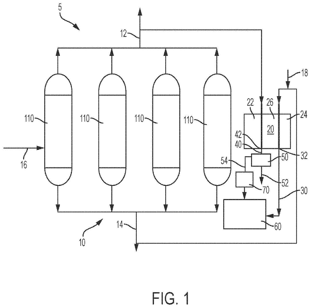
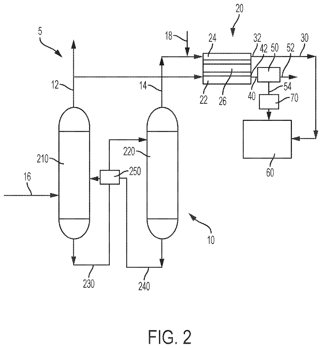
[0012]Reference will now be made in detail to embodiments of the method for capturing CO2 to produce high-purity CO2 in a hydrocarbon facility of the present disclosure and associated system. Though the CO2 capture systems 5 of FIGS. 1 and 2 are provided as exemplary, it should be understood that the present systems and methods encompass other configurations.

[0013]Hydrogen is produced in oil refineries and other hydrocarbon treatment facilities by a variety of methods. These methods of producing hydrogen include steam reforming, partial oxidation, auto-thermal reforming and non-catalytic partial oxidation of light hydrocarbons as well as other non-conventional methods.

[0014]In one or more embodiments, H2 and CO2 are produced via sequential steam reforming and a water gas shift. Specifically, in steam reforming, H2 and CO are produced in a 3:1 ratio from methane (CH4) and water. The combination of H2 and CO is commonly referenced as syngas. Steam reforming produces the H2 and CO from...


PUM

PropertyMeasurementUnit
pressureaaaaaaaaaa
operating temperatureaaaaaaaaaa
inlet temperatureaaaaaaaaaa

Abstract

Embodiments of methods for capturing high-purity CO2 in a hydrocarbon facility and related systems are provided. The method comprises operating a hydrogen plant to generate a high-purity hydrogen stream and a CO2 rich stream with a CO2 concentration above 30%; introducing the high-purity hydrogen stream into an anode of a molten carbonate fuel cell; introducing the CO2 rich stream and O2 into a cathode of the molten carbonate fuel cell; reacting CO2 and O2 within the cathode to produce carbonate and a cathode exhaust stream from a cathode outlet; reacting carbonate from the cathode with H2 within the anode to produce electricity and an anode exhaust stream from an anode outlet, the anode exhaust stream comprising CO2 and H2O; separating the CO2 in the anode exhaust stream in one or more separators to form a pure CO2 stream and a H2O stream; and collecting the pure CO2 stream.

Description

BACKGROUNDField[0001]Embodiments of the present disclosure generally relate to a methods and systems for capturing high-purity CO2 in a hydrocarbon facility and more specifically relate to operating a molten carbonate fuel cell (MCFC) with the H2 generated from a hydrogen plant to manage CO2 produced in the hydrogen plants while generating electricity.Technical Background[0002]Hydrogen is commonly produced in oil refineries and other hydrocarbon treatment facilities as part of plant operations. The hydrogen is generally produced by steam reforming, partial oxidation, auto-thermal reforming and non-catalytic partial oxidation of light hydrocarbons. The hydrogen production process typical additionally produces CO2. The hydrogen and CO2 may be separated yielding a stream of waste CO2 and other non-hydrogen constituents such as methane (CH4) and CO. Common practice is to simply recycle the CO2 containing stream back to a steam reformer to utilize any non converted methane and produce mo...

Claims


Application Information

Patent Timeline
Patent Type & Authority Patents(United States)
IPC IPC(8): B01D53/00H01M8/0662C01B3/38H01M8/0668H01M8/14B01D53/047C01B3/48H01M8/0612
CPCH01M8/0668C01B3/48H01M8/145C01B3/384B01D53/047H01M8/0687H01M8/0618C01B2203/0415C01B2203/066C01B2203/0475C01B2203/0233H01M2008/147C01B2203/148C01B2203/043Y02C20/40Y02E60/50Y02P30/00Y02C20/20
Inventor AL HUNAIDY, ALI SHAKERSOUENTIE, STAMATIOS
Owner SAUDI ARABIAN OIL CO
Why Eureka
Try Eureka