Supercharge Your Innovation With Domain-Expert AI Agents!

Non-fluorescent imaging optical sectioning method and device based on annular off-axis illumination focal plane conjugation

a fluorescence imaging and optical sectioning technology, applied in the field of optical sectioning of non-fluorescent imaging, can solve the problems of difficult to obtain microscopic images of the inner three-dimensional structure of the sample, more difficult to achieve than the optical sectioning technique of fluorescence imaging, etc., to achieve convenient dynamic sample imaging, fast imaging speed, and simple and convenient

Active Publication Date: 2020-05-05
JINAN UNIVERSITY
View PDF16 Cites 0 Cited by
  • Summary
  • Abstract
  • Description
  • Claims
  • Application Information

AI Technical Summary

Benefits of technology

The present invention provides a non-fluorescent imaging optical sectioning method that uses annular off-axis illumination focal plane conjugation. This method improves the speed of optical-section imaging and avoids the potential biotoxicity and phototoxicity of fluorescence imaging methods to samples. Compared to other techniques, this invention has the advantage of being simpler and more efficient.

Problems solved by technology

The traditional wide-field microscope, which is widely used in the fields of biomedical and material science, is difficult to obtain microscopic images of an inner three-dimensional structure of a sample due to its large depth of field.
However, for a non-fluorescent sample, only scattered light of the sample can be used for imaging, which is more difficult to achieve than the optical sectioning technique of fluorescence imaging due to the relatively weak signal-to-noise ratio.
Obviously, the imaging method of point-by-point scanning is time-consuming and very disadvantageous to image dynamic objects.
Therefore, there are limitations to the optical-section imaging of living organisms.
The structured light illumination microscopy can also be used to perform optical-section imaging of a non-fluorescent sample, but the illumination device is relatively complex due to the use of structured light illumination.
In addition, when using fluorescence imaging, the sample needs to be fluorescently labeled, and the fluorescence labeling may have biotoxicity, thus affecting the sample.

Method used


Image

  • Non-fluorescent imaging optical sectioning method and device based on annular off-axis illumination focal plane conjugation
  • Non-fluorescent imaging optical sectioning method and device based on annular off-axis illumination focal plane conjugation
  • Non-fluorescent imaging optical sectioning method and device based on annular off-axis illumination focal plane conjugation

Examples


embodiment 1

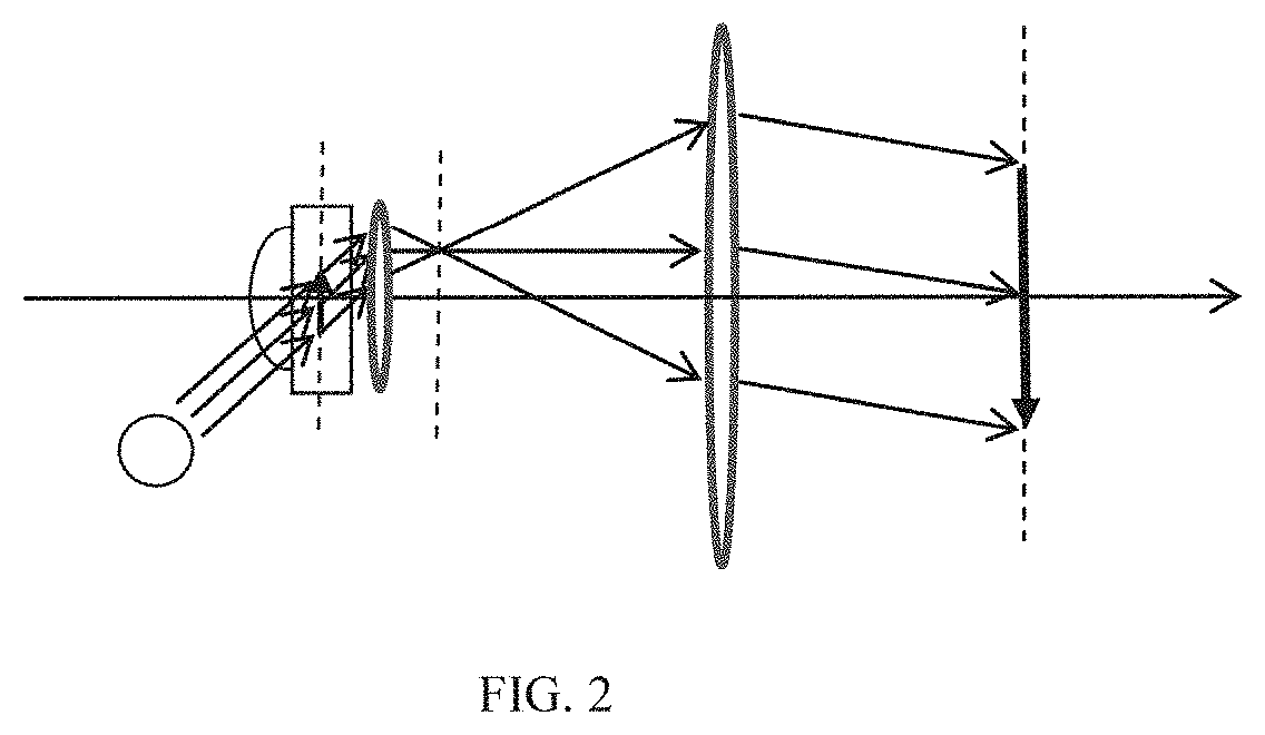
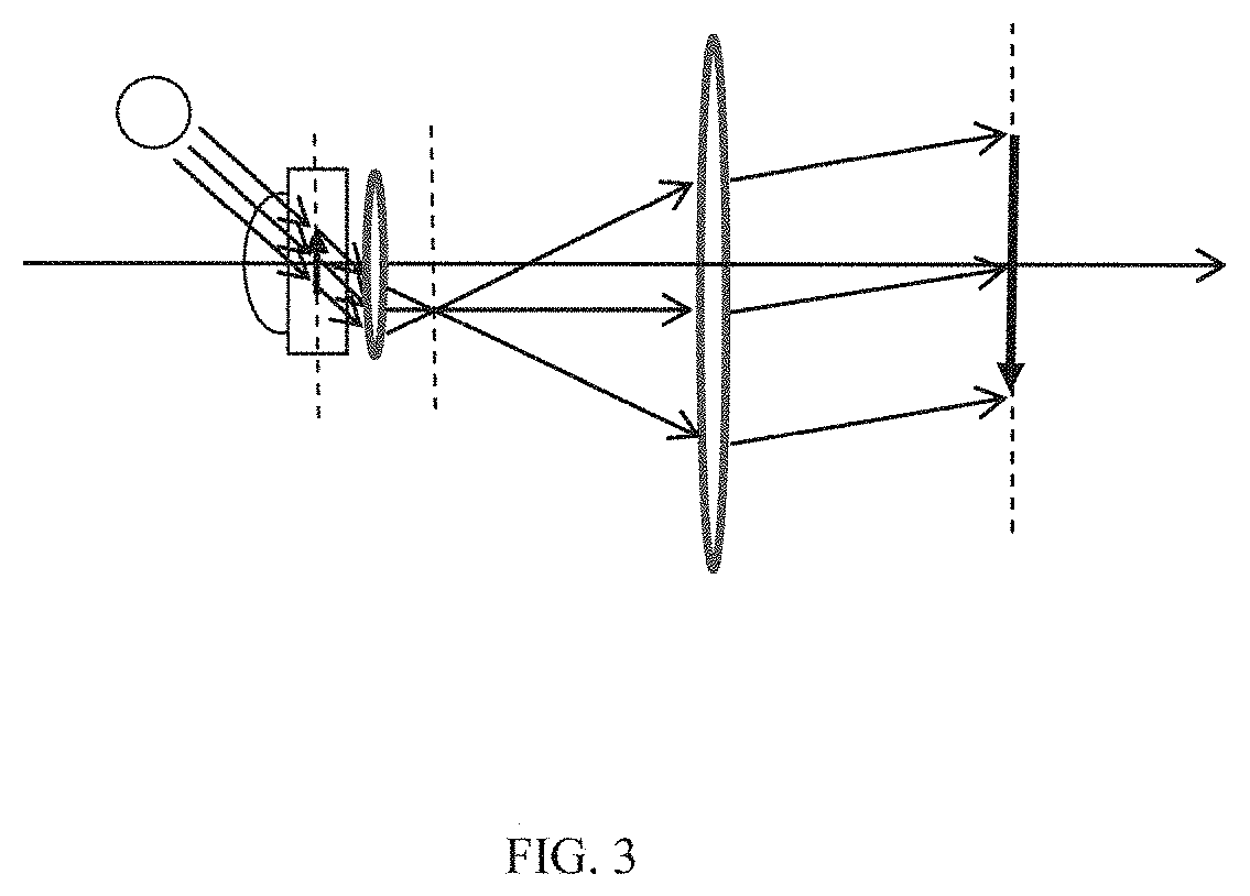
[0046]In a traditional bright-field optical microscope, due to the limitation of diffraction, an axial resolvable distance is generally larger than 600 nm, and light beams involved in imaging are mainly beams near an optical axis of an objective lens. In order to improve the axial resolution of microscopic imaging and obtain ultra-thin optical sections, the invention proposes to adopt an objective lens with a large numerical aperture and use light beams at a large inclination angle off the optical axis of the objective lens for imaging. In various conventional microscopic imaging systems, the beams involved in imaging are mainly near-axis beams, which is the biggest difference between the present invention and the conventional microscopic imaging technology. Although a dark-field microscope adopts an off-axis illumination mode, its purpose is to prevent direct lights of the illumination beams from entering the objective lens for imaging, ensuring that the background is a dark field ...

embodiment 2

[0061]As shown in FIG. 1, this embodiment discloses a non-fluorescent imaging optical sectioning device based on annular off-axis illumination focal plane conjugation, including sequentially an annularly distributed light source 1, an objective lens 4, a tube lens 6 and a camera 7 to form an infinity-corrected optical system. Off-axis light beams emitted by the annularly distributed light source 1 illuminate a sample placed on a sample stage 3 at an inclination angle θ. The sample stage 3 is arranged between the annularly distributed light source 1 and the objective lens 4, and is translatable along an optical axis of the objective lens 4 in a z direction under the control of a translation mechanism 8. The objective lens 4 and the tube lens 6 have the same optical axis which passes through the center of the annularly distributed light source 1. A photosensitive surface of the camera 7 coincides with an image focal plane of the tube lens 6. A computer 9 controls the movement of the t...

embodiment 3

[0064]As shown in FIG. 8, this embodiment discloses another non-fluorescent imaging optical sectioning device based on annular off-axis illumination focal plane conjugation, which uses a 60-fold objective lens 4 with a numerical aperture of 1.49 and a tube lens 6 with a focal length of 200 mm to form an infinity-corrected optical system 100. 80 white LED light sources are uniformly distributed on the inner surface of an annular aluminum alloy with a diameter of 132 mm to form an annularly distributed light source 1, each LED having the same power of 0.15 W. A power supply controller controls the 80 light sources to be lit at the same time. The light beams emitted by each LED light source illuminate a hemispherical plano-convex lens used as the refractive index matching lens 2, which is made of K9 glass material and has a spherical radius of 10 mm. The bottom surface of the hemispherical plano-convex lens is bonded to the slide glass encapsulating the sample by cedar oil and fixed on...


PUM

PropertyMeasurementUnit
included angleaaaaaaaaaa
azimuth angleaaaaaaaaaa
refractive indexaaaaaaaaaa

Abstract

The invention discloses a non-fluorescent imaging optical sectioning method and device based on annular off-axis illumination focal plane conjugation. In an infinity-corrected optical system constituted by an objective lens with a large numerical aperture and a tube lens, off-axis light beams are used for bright-field microscopic imaging of a non-fluorescent sample; light beams emitted by M sub-sources which form an annularly distributed light source illuminate the sample off-axis at a large inclination angle; all sub-sources are lit to illuminate the sample at the same time, forming a superposed image of the sample illuminated by the M sub-sources individually on an image focal plane of the tube lens, and the camera shoots the image to obtain an optical-section image of a layer in the sample; and under the control of a translation mechanism, a sample stage allows different layers in the sample to coincide with an object focal plane of the objective lens to obtain optical-section images of multiple layers in the sample.

Description

CROSS-REFERENCE TO RELATED APPLICATIONS[0001]This application is a continuation of International Patent Application No. PCT / CN2018 / 079702, filed on Mar. 21, 2018, which claims the benefit of priority from Chinese Application No. 201710324978.7, filed on May 10, 2017. The contents of the aforementioned applications, including any intervening amendments thereto, are incorporated herein by reference in its entirety.TECHNICAL FIELD[0002]The invention relates to the field of optical imaging technology, and particularly relates to a non-fluorescent imaging optical sectioning method and device based on annular off-axis illumination focal plane conjugation, in particular to focal plane conjugation optical sectioning microscopy by using an annular beam, which is off from the optical axis of an objective lens, illuminating a sample.BACKGROUND OF THE PRESENT INVENTION[0003]The traditional wide-field microscope, which is widely used in the fields of biomedical and material science, is difficult...

Claims


Application Information

Patent Timeline
Patent Type & Authority Patents(United States)
IPC IPC(8): G02B21/12G02B21/36G02B21/02G02B21/26G02B21/10G02B21/08G02B21/33
CPCG02B21/26G02B21/10G02B21/367G02B21/084G02B21/02G02B21/12G02B21/33G02B21/06G02B21/36
Inventor ZHONG, JINGANGMA, XIAO
Owner JINAN UNIVERSITY
Features
  • R&D
  • Intellectual Property
  • Life Sciences
  • Materials
  • Tech Scout
  • Unparalleled Data Quality
  • Higher Quality Content
  • 60% Fewer Hallucinations
Learn More