
Low-noise microwave amplifier utilizing superconductor-insulator-superconductor junction

a microwave amplifier and superconductor technology, applied in the direction of dissimilar material junction devices, superconductor devices, basic electric elements, etc., can solve the problems of low power consumption of the device itself, the inability to achieve related-art amplifiers, and the limitation of the number of amplifiers capable of being mounted to cryogenic stages. , to achieve the effect of reducing the heat load on the refrigerator and reducing power consumption

Active Publication Date: 2020-06-09
INTER UNIV RES INST NAT INST OF NATURAL SCI
View PDF2 Cites 1 Cited by
  • Summary
  • Abstract
  • Description
  • Claims
  • Application Information

AI Technical Summary

Benefits of technology

The present invention is a low-noise amplifier that has several technical benefits. Firstly, it operates at a low noise temperature, making it easy to cool and maintain. Secondly, it has a wide frequency band, which is useful for a variety of applications. Lastly, it uses a mixer called an SIS mixer which is ultra-efficient and consumes very low power, which means that multiple amplifiers can be mounted without overwhelming the cooling system. Overall, this new amplifier offers a highly effective and efficient solution for low-noise amplification.

Problems solved by technology

Those demands cannot be achieved with the related-art amplifiers disclosed in the above-cited literatures.
More specifically, in one example of the related-art semiconductor amplifiers in which a tunnel diode is used, heat is generated due to application of direct current power, and the number of amplifiers capable of being mounted to a cryogenic stage has to be limited.
Furthermore, the related-art superconducting amplifier requires a dilution refrigerator having high cooling capacity for the reason that the amplifier is assumed to be operated at 100 mK or below although the power consumption of the device itself is low.
This causes a problem that the scale of a system is increased and large power is needed in operation of the system.
When large power is needed, a difficulty occurs in practical use of the system in many cases because many astronomical observation sites are present in places where available power infrastructures are limited, such as a satellite, a high mountain, a desert, and the South Pole.
However, because a frequency filter needs to be used to suppress a signal component for pumping near a pump frequency for parameter excitation at which a maximum gain is obtained, a problem arises in that an actually usable frequency band is restricted.

Method used


Image

  • Low-noise microwave amplifier utilizing superconductor-insulator-superconductor junction
  • Low-noise microwave amplifier utilizing superconductor-insulator-superconductor junction
  • Low-noise microwave amplifier utilizing superconductor-insulator-superconductor junction

Examples


example 1

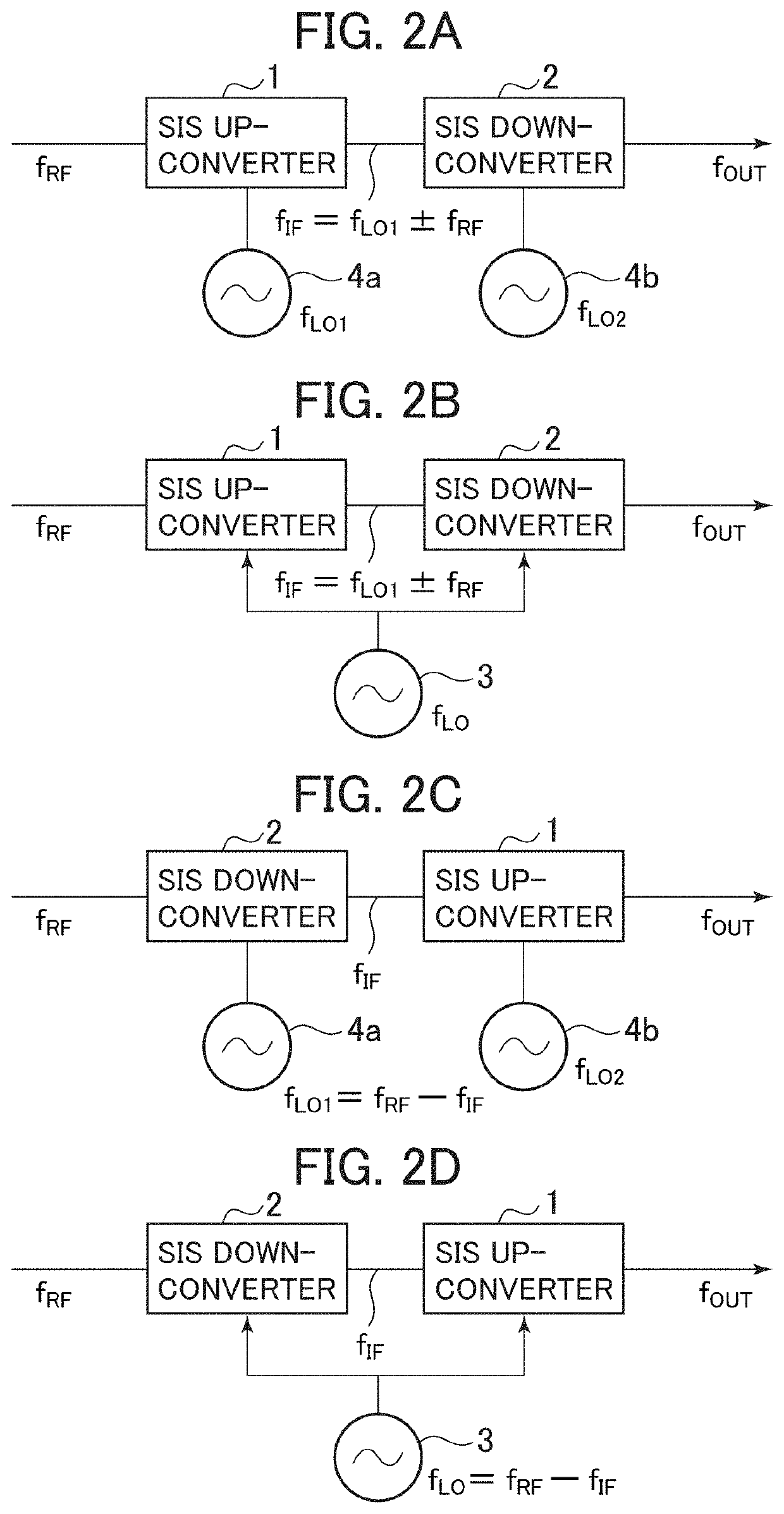
[0058]FIGS. 2A to 2D illustrate basic exemplary configurations of the present invention. Of FIGS. 2A to 2D, FIG. 2A illustrates an example in which one frequency up-converter and one frequency down-converter are connected in series (i.e., in tandem or in cascade) and are operated as an amplifier. An up-converter 1 and a down-converter 2 are each a quasiparticle mixer utilizing a superconductor-insulator-superconductor (SIS) junction. At temperature not more than the temperature at which the SIS operates as a superconducting element, each of the SIS quasiparticle mixers operates as a double side band (DSB) mixer for a local oscillation frequency signal at a frequency not less than the gap frequency, which is a frequency equivalent (eΔVg / h: e denotes the elementary charge, and h denotes the Plank's constant) of a gap voltage width (ΔVg). In the configuration illustrated in FIG. 2A, an input signal having a frequency fRF is frequency-converted to fIF (=fLO±fRF) with a gain GUP using th...

example 2

[0074]FIG. 5A is a block diagram of a low-noise microwave amplifier fabricated as a prototype for experimental evaluation of a gain. SIS mixers used as the up-converter 1 and the down-converter 2 are the same as the converters designed in a 100-GHz band. For the purpose of suppressing interference in a circuit, an attenuator 8 is inserted between the up-converter 1 and the down-converter 2.

[0075]The attenuator 8 operates as an isolator. In other words, characteristics required for the isolator used in the present invention are to suppress a signal propagating from the second quasiparticle mixer to the first quasiparticle mixer. A directional coupler or a microwave isolator, for example, may also be used instead of the attenuator.

[0076]FIG. 5B depicts frequency dependency of the gain. Despite the above-described attenuator is arranged, a gain of about 3 dB is obtained in a 5-GHz band when the LO frequency is about 92 GHz. Since an attenuation of the attenuator at that frequency is ab...

example 3

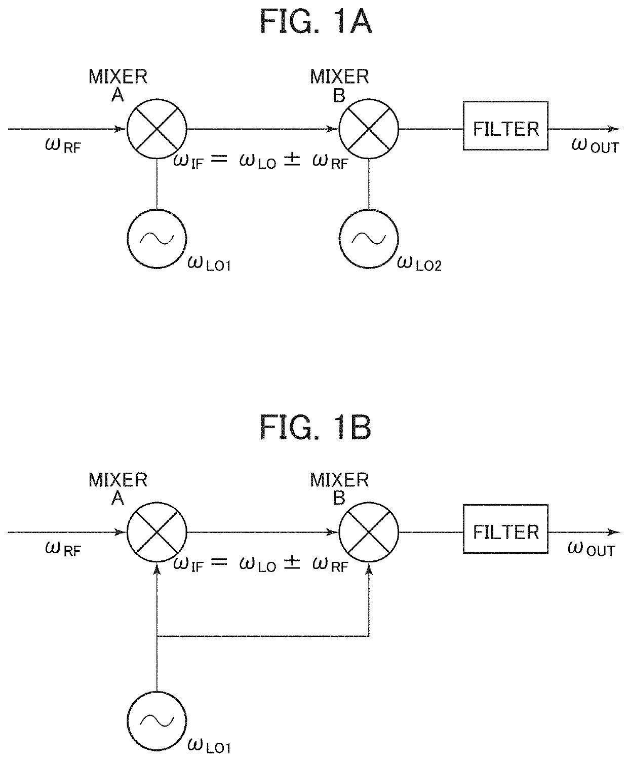
[0078]As described above in relation to FIG. 1A, it is also possible to perform frequency conversion while the input signal is amplified, by using signals having different frequencies as the local oscillation signals for the up-converter and the down-converter. On that occasion, introducing a plurality of local oscillation signals into the quasiparticle mixers from external signal sources, respectively, means that external heats are also introduced together into a cryogenic region. Therefore, oscillation elements each having a similar structure to that of the SIS is desirably formed on the same substrate on which the above-described converters are formed. As such an oscillation element, there is Josephson oscillator using a Josephson current. It is known that thermal noise from an oscillation element under cryogenic environments is very low. Thus, a noise figure in the amplifier of the present invention can be easily improved by using that type of oscillation element. The above poin...


PUM


Abstract

A low-noise wide band amplifier is realized utilizing a superconductor-insulator-superconductor (SIS) junction, quasiparticle frequency mixers connected in tandem or in cascade, a first quasiparticle mixer performs first frequency mixing with use of a first local signal having a frequency not less than twice a frequency of an input signal to the first quasiparticle mixer, a second quasiparticle mixer performs second frequency mixing with use of a second local signal having a frequency not more than twice a frequency of an input signal to the second quasiparticle mixer, and signal amplification is performed through frequency conversion by extracting, from among a plurality of signals generated with the first and the second frequency mixing, a signal in a frequency band not more than a frequency band of the signal before the first frequency mixing and the second frequency mixing, using a transmission line or a filter.

Description

BACKGROUND OF THE INVENTION1. Field of the Invention[0001]The present invention relates to a low-noise microwave amplifier in which an up-converter and a down-converter, each utilizing a superconductor-insulator-superconductor (SIS) junction, are connected in series.[0002]A low-noise electromagnetic amplifier is used in various fields. In a radio astronomical field, for example, the low-noise electromagnetic amplifier is used to directly amplify an observed signal or to amplify an intermediate frequency signal obtained after heterodyne conversion, aiming to observe weak electromagnetic waves from the astronomical object. Similarly, in a quantum-bit research field, the low-noise electromagnetic amplifier is used to detect a weak signal from a quantum bit circuit, and is required to have ultralow-noise properties as in the radio astronomical field. In the above-described fields, an amplifier using a semiconductor, which operates at ultralow temperature and has wide band characteristic...

Claims


Application Information

Patent Timeline
Patent Type & Authority Patents(United States)
IPC IPC(8): H03F19/00H01L39/22H01L27/18H01L21/768H01L29/43H01L23/498H01L23/532H01L21/3205H10N69/00
CPCH01L39/223H03F19/00H01L21/76891H01L23/53285H01L29/437H01L27/18H01L21/32058H01L23/49888H10N60/12H10N69/00
Inventor UZAWA, YOSHINORIKOJIMA, TAKAFUMI
Owner INTER UNIV RES INST NAT INST OF NATURAL SCI
Learn More