Patient interface and method for making same

a patient interface and interface technology, applied in the field of respiratory disorders, can solve the problems of csr harm, cardiovascular disease and brain damage, excessive daytime somnolence, etc., and achieve the effects of improving comfort, cost, efficacy, and ease of us

Active Publication Date: 2020-06-23
RESMED LTD
View PDF69 Cites 0 Cited by
  • Summary
  • Abstract
  • Description
  • Claims
  • Application Information

AI Technical Summary

Benefits of technology

[0038]A mandibular repositioning device (MRD) is one of the treatment options for sleep apnea. It is a custom made, adjustable oral appliance available from a dentist that holds the lower jaw in a forward position during sleep. This mechanical protrusion expands the space behind the tongue, puts tension on the pharyngeal walls to reduce collapse of the airway and diminishes palate vibration.BRIEF SUMMARY OF THE TECHNOLOGY
[0039]The present technology is directed towards providing medical devices used in the diagnosis, amelioration, treatment, or prevention of respiratory disorders having one or more of improved comfort, cost, efficacy, ease of use and manufacturability.
[0044]One aspect of one form of the present technology is a patient interface with a seal-forming structure that is removable for cleaning. It is the desire of the present technology to provide a patient interface that is light-weight compared to prior art patient interfaces, more unobtrusive compared to prior art patient interfaces and more quiet in use compared to prior art patient interfaces. It is also desirable to provide a patient interface that is intuitive to a patient when connecting mask components prior to commencement of therapy and is also simple to adjust and wear for therapy.
[0056]Another aspect of one form of the present technology is a cushion member for a patient interface for delivery of a supply of pressurised air or breathable gas to an entrance of a patient's airways, the cushion member including a retaining structure for repeatable engagement with and disengagement from a frame member, and a seal-forming structure connected to the retaining structure, the seal-forming structure serving both nares of the patient with a single orifice. The seal-forming structure is made from a first material and the retaining structure is made from a second material that is different from the first material and is more rigid than the first material. The seal-forming structure has a substantially flat lower wall to alleviate pressure on the patient's upper lip.
[0057]An aspect of one form of the present technology is a method of manufacturing the patient interface described herein. It is a desire of the present technology to provide a method of manufacture that has less complexity than methods of manufacturing prior art patient interfaces to increase manufacturing efficiency, uses less raw materials and requires less assembly time by operators.
[0059]Another aspect of one form of the present technology is a headgear clip for a positioning and stabilising structure of a patient interface including a mechanical structure to mechanically engage the headgear clip to a headgear connection point of a frame assembly and allow the headgear clip to rotate relative to the headgear connection point, a magnet to magnetically engage the headgear clip with the headgear connection point, and a slot to receive a headgear strap passing therethrough, wherein the mechanical structure prevents linear displacement of the headgear clip in a direction substantially parallel to the Frankfort horizontal direction when headgear tension is applied and the mechanical structure includes a raised wall that defines a space adapted to receive the headgear connection point. The raised wall may be in the shape of a semi-circle, and the headgear connection point may include a cylindrical portion providing a raised surface structured to engage the raised wall. The magnet may be held within the headgear clip by a top layer of plastic material and a bottom layer of plastic material. The mechanical structure may be a raised wall projecting away from the bottom layer of plastic material. The raised wall may project from a circumferential portion around the magnet. The raised wall may have a semi-circular cross-section. The magnet may be fully encased in plastic material. The slot may be elongate having its longitudinal axis oriented parallel with a nominal vertical axis in use. When the headgear clip is engaged with the headgear connection point and headgear tension is applied, the slot may be unobstructed by the lower arm and frame assembly. The headgear connection point may comprise a magnet. The magnet of the headgear connection point may be fully encased in plastic material. The magnet of the headgear connection point may be fully encased within the lower arm. The headgear connection point may be a raised surface from a lower arm of the frame assembly such it abuts the raised wall when headgear tension is applied. When headgear tension is applied by adjusting the length of the headgear strap, the headgear clip may maintain mechanical and magnetic engagement with the lower arm and rotate relative to the lower arm. The magnet of the headgear clip and / or the headgear connection point may be a ferromagnetic material, permanent magnet or electromagnet.

Problems solved by technology

It often causes excessive daytime somnolence, and it may cause cardiovascular disease and brain damage.
It is possible that CSR is harmful because of the repetitive hypoxia.
In some patients CSR is associated with repetitive arousal from sleep, which causes severe sleep disruption, increased sympathetic activity, and increased afterload.
Symptoms include dyspnea, morning headache and excessive daytime sleepiness.
Some NMD patients are characterised by progressive muscular impairment leading to loss of ambulation, being wheelchair-bound, swallowing difficulties, respiratory muscle weakness and, eventually, death from respiratory failure.
Symptoms of respiratory failure in NMD include: increasing generalised weakness, dysphagia, dyspnea on exertion and at rest, fatigue, sleepiness, morning headache, and difficulties with concentration and mood changes.
Chest wall disorders are a group of thoracic deformities that result in inefficient coupling between the respiratory muscles and the thoracic cage.
Scoliosis and / or kyphoscoliosis may cause severe respiratory failure.
Symptoms of respiratory failure include: dyspnea on exertion, peripheral oedema, orthopnoea, repeated chest infections, morning headaches, fatigue, poor sleep quality and loss of appetite.
A range of patient interface devices are known, however a number of them suffer from being one or more of obtrusive, aesthetically undesirable, poorly fitting, difficult to use and uncomfortable especially when worn for long periods of time or when a patient is unfamiliar with a system.
Masks designed solely for aviators, as part of personal protection equipment or for the administration of anaesthetics may be tolerable for their original application, but nevertheless be undesirably uncomfortable to be worn for extended periods, for example, while sleeping.
Furthermore, if the shape of the seal-forming structure does not match that of the patient, it may crease or buckle in use, giving rise to leaks.
Some patients may find it inconvenient to constantly apply and remove an adhesive to their face.
Many such harnesses suffer from being one or more of ill-fitting, bulky, uncomfortable and awkward to use.
One known problem is associated with the fact that a rigidiser permanently attached (e.g. laminated or stitched) to a large area of the stretchable material limits the stretchable length of the material, thus affecting the elastic properties of the entire headgear.
Another issue concerns cleaning the headgear which would require both the rigidiser and stretchable material to be washed together as they are permanently attached to each other.
Many such vents are noisy.
Others may block in use and provide insufficient washout.
Some vents may be disruptive of the sleep of a bed-partner of the patient, e.g. through noise or focussed airflow.
Some vents cannot be properly cleaned and must be discarded after they become blocked.

Method used


Image

  • Patient interface and method for making same
  • Patient interface and method for making same
  • Patient interface and method for making same

Examples


Embodiment Construction

[0165]Before the present technology is described in further detail, it is to be understood that the technology is not limited to the particular examples described herein, which may vary. It is also to be understood that the terminology used in this disclosure is for the purpose of describing only the particular examples discussed herein, and is not intended to be limiting.

Treatment Systems

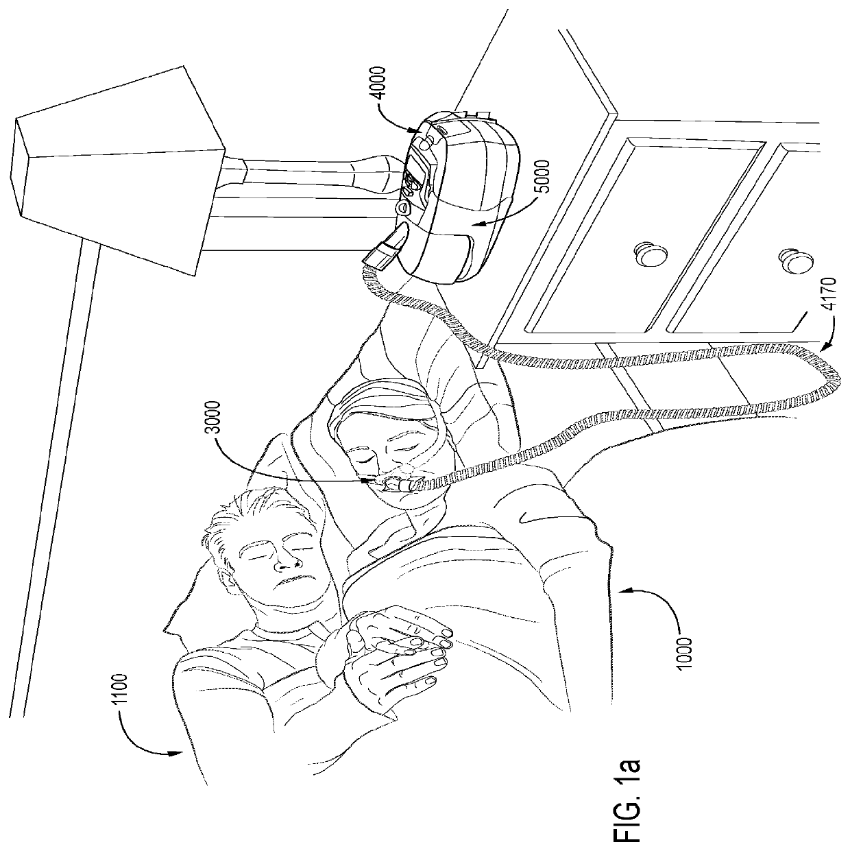
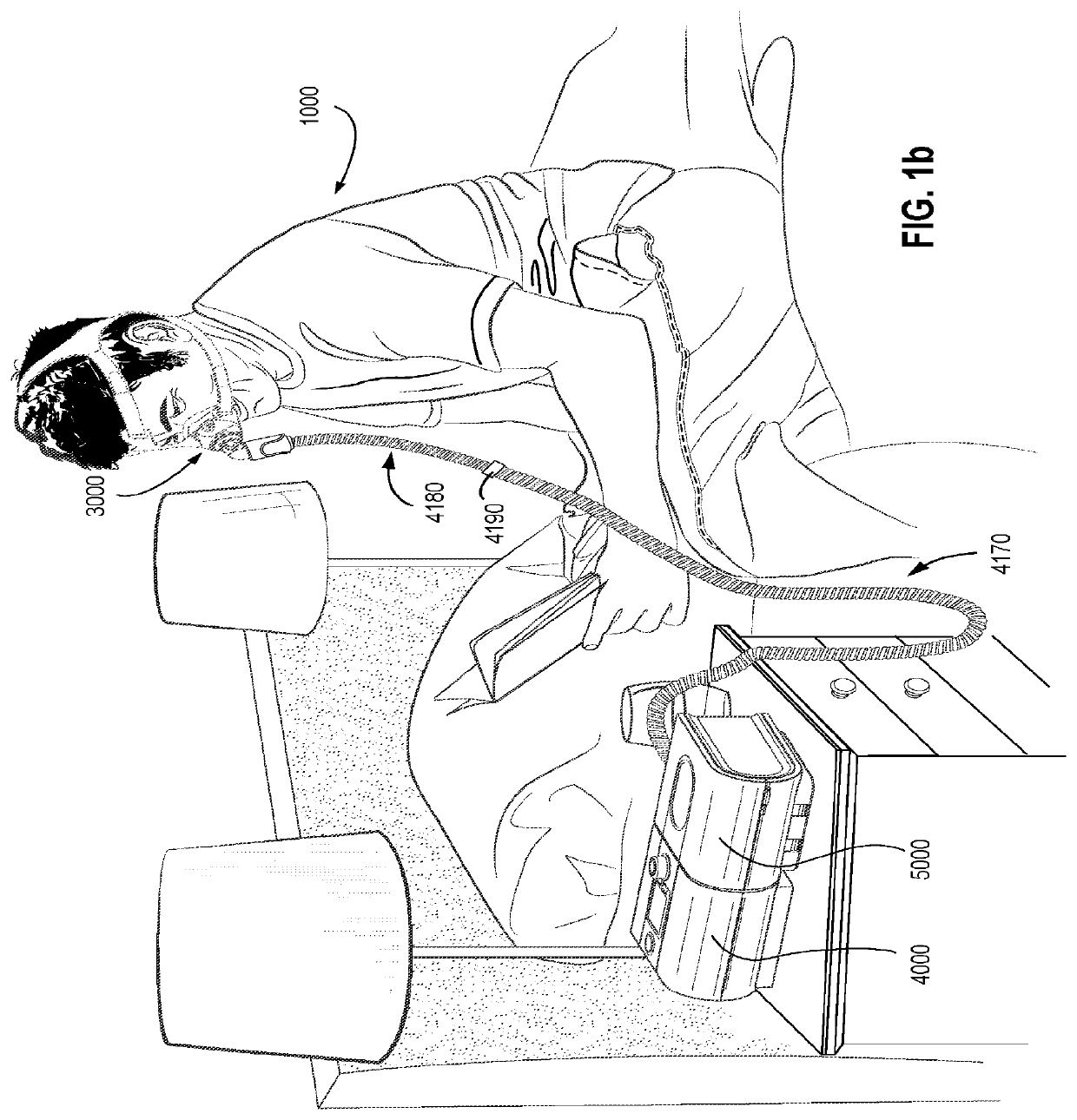
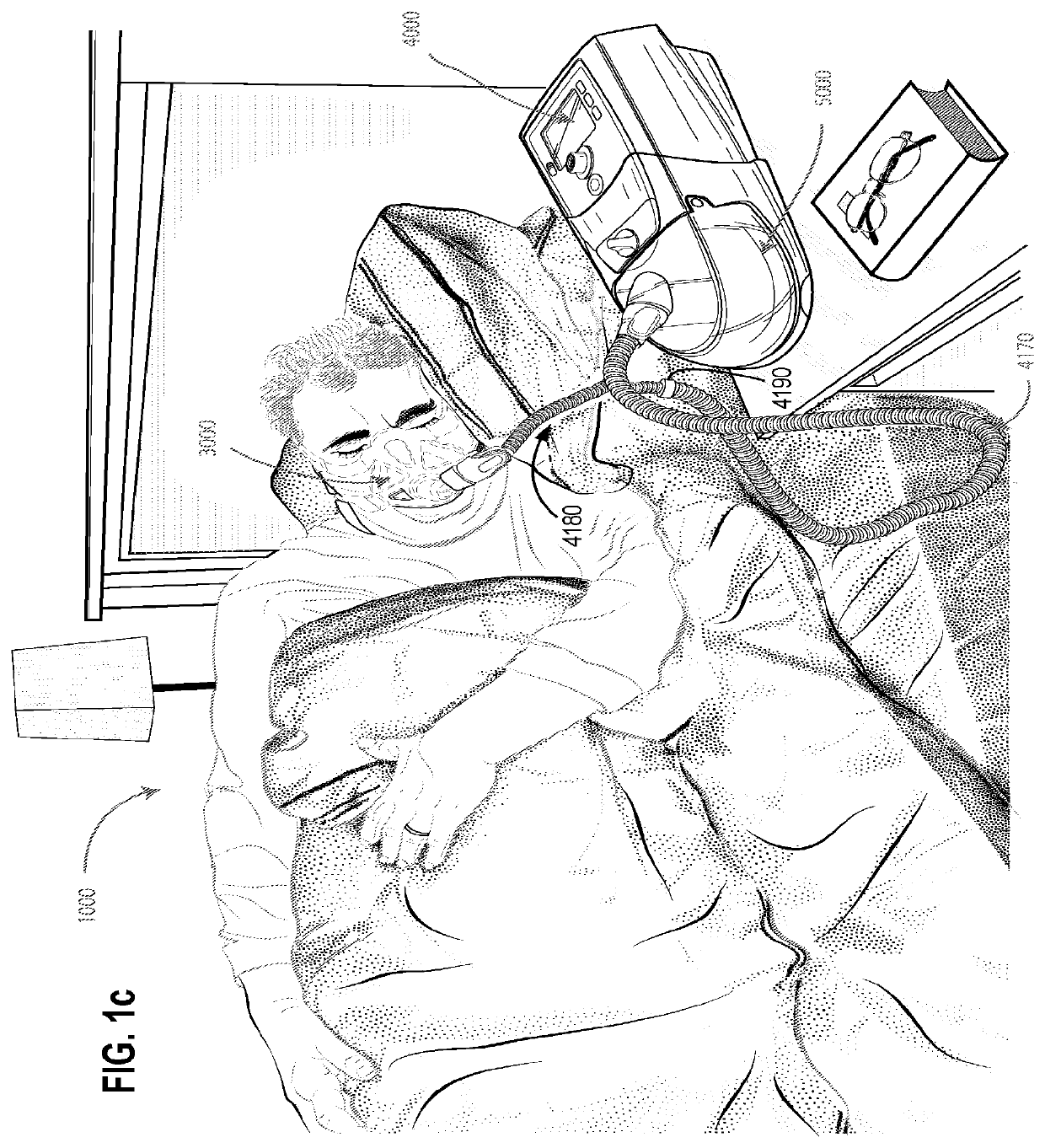
[0166]In one form, the present technology comprises apparatus for treating a respiratory disorder. The apparatus may comprise a flow generator or blower for supplying pressurised respiratory gas, such as air, to the patient 1000 via an air circuit 4170 leading to a patient interface 3000, as shown in FIG. 1a.

Therapy

[0167]In one form, the present technology comprises a method for treating a respiratory disorder comprising the step of applying positive pressure to the entrance of the airways of a patient 1000.

Nasal CPAP for OSA

[0168]In one form, the present technology comprises a method of treating ...


PUM


Abstract

A nasal patient interface for delivery of a supply of pressurised air or breathable gas to an entrance of a patient's airways comprising: a cushion member that includes a retaining structure and a seal-forming structure permanently connected to the retaining structure; a frame member attachable to the retaining structure; and a positioning and stabilising structure releasably attachable to the frame member.

Description

CROSS-REFERENCE TO RELATED APPLICATIONS[0001]This application is the U.S. national phase of International Application No. PCT / AU2014 / 000021 filed 15 Jan. 2014, which designated the U.S. and claims the benefit of U.S. Provisional Appln. Nos. 61 / 811,385 filed on 12 Apr. 2013; 61 / 817,674 filed on 30 Apr. 2013; 61 / 823,192 filed on 14 May 2013; 61 / 888,357 filed on 8 Oct. 2013; and 61 / 915,320 filed Dec. 12, 2013; EP Non-Provisional Appln. No. 13163546.8 filed on 12 Apr. 2013; AU Provisional Appln. Nos. 2013900168 filed on 18 Jan. 2013; 2013902305 filed on 24 Jun. 2013; 2013902945 filed on 6 Aug. 2013; and 2013903509 filed on 12 Sep. 2013. Each of the applications referenced above is incorporated herein by reference in its entirety.[0002]A portion of the disclosure of this patent document contains material which is subject to copyright protection. The copyright owner has no objection to the facsimile reproduction by anyone of the patent document or the patent disclosure, as it appears in t...

Claims


Application Information

Patent Timeline
Patent Type & Authority Patents(United States)
IPC IPC(8): A61M16/06A61M16/08A61M16/10
CPCA61M16/0683A61M16/0875A61M2205/42A61M16/0825A61M2210/0618A61M16/107A61M16/0616A61M16/1055A61M2207/00
Inventor CULLEN, CHRISTOPHER SAMUELGUNEY, MEMDUHEVES, MATTHEWLA GUZZA, MICHAEL CHARLESVON MOGER, LOCHLANSCHEINER, RUPERT CHRISTIANWAGNER, STEWART JOSEPHMAY, FREDERICK ARLETGOLDSPINK, LACHLAN RICHARDFORRESTER, MARTINJOURDAN, RALPHAMARASINGHE, AMAL SHIRLEYSKIPPER, CHRISTOPHER SCOTTFORMICA, JUSTIN JOHNDUNN, JESSICA LEAEDWARDS, CRAIG DAVID
Owner RESMED LTD
Why Eureka
Try Eureka