Process for calibrating a sensor, automated method for online monitoring of the changes to a liquid body and associated sensor

a technology of liquid body and sensor, applied in the field of measuring instruments, can solve the problems of high cost of maintenance operations, relatively difficult operation of wind turbines, and sensitive to wear or corrosion phenomena, and achieve the effect of reliable measurement and satisfactory mechanical properties

Active Publication Date: 2020-10-27
WIKA
View PDF9 Cites 4 Cited by
  • Summary
  • Abstract
  • Description
  • Claims
  • Application Information

AI Technical Summary

Benefits of technology

[0017]The calibration process according to the invention therefore makes it possible to do without samples of liquid body to be analyzed and to do without introducing such samples into an installation that incorporates the sensor, using, as reference spectrum, a reference spectrum based on the components of the casing of the measuring cell of said sensor. The invention therefore does the complete opposite of the traditional calibration techniques, which consist of using representative samples of the product to be analyzed. Indeed, the process according to the invention bases the calibration on a material different from that which is analyzed, namely the material of the casing. The calibration process can therefore be implemented automatically, without having to place a sample of the liquid body in the cell of the sensor, or manually by a person without specific chemical skills, in particular a roaming agent responsible for maintaining wind turbines or a refining technician.
[0028]The invention also relates to a sensor that in particular makes it possible to carry out the process and the method mentioned above, and more specifically, a sensor for using x-ray fluorescence technology to determine the overall content, in a predetermined chemical element, of a liquid body. This sensor comprises an x-ray source, an x-ray detector and a cell intended to contain a sample of the liquid body to be analyzed, this cell being equipped with a wall forming a window for the passage of the rays coming from the source or going toward the x-ray detector, this wall being made from polyethylene terephthalate.
[0029]Owing to this aspect of the invention, the sensor, which operates using x-ray fluorescence technology, allows a reliable measurement of the overall content of a predetermined chemical element in a liquid body. Within the meaning of the present invention, the overall content of a chemical element in a liquid body is the content of dissolved element, and in particular of said chemical element, in said liquid body. Advantageously, the sensor that uses the technology is a sensor of the iron content in the liquid body. The measurement performed is not significantly affected by the wall making up the passage window for the x-rays. Indeed, this wall, made from polyethylene terephthalate (PET), can be provided with a relatively insignificant thickness, in particular less than 200 μm (micrometers), while having satisfactory mechanical properties to withstand the pressure and vibration forces within a measuring installation. The component material of the wall also allows it not to be altered by the liquid body circulating in the cell.

Problems solved by technology

Maintenance operations are expensive, and currently, the inspection of the lubricant liquid of the wind turbines is done, after withdrawal, in a laboratory.
Wind turbines are sensitive to wear or corrosion phenomena; their access difficulties require these analyses to be done on site, in particular to monitor the overall particulate iron content of the oil, this content resulting from abrasion phenomena.
This requires training staff and carrying elaborate equipment on site, the operation of which is relatively difficult to master, even by trained staff.
Furthermore, this increases the crew's workload.
In practice, the oil flow rate leaving the engine is low, and the flow leaving the engine is made up of droplets that stream inside a pipe, to the point that it is not certain that the functional component is supplied with a sufficient oil flow rate for the measurements it performs to be accurate.
Furthermore, laboratory equipment, like that known from U.S. Pat. No. 6,233,307, which could make it possible to detect the dissolved iron content of an oil for a wind turbine, is difficult to transport and complex to use, which makes it relatively impractical, even for roaming staff trained to that end.
This type of equipment also must be calibrated regularly, which is complex to do.
Such an approach can be considered in the laboratory, but cannot be implemented in practice in an on-board installation, which is not provided for that purpose.
Similar problems arise for sensors for determining the content of a liquid body in another predetermined chemical element, in particular calcium, sulfur, vanadium, chromium, molybdenum, copper, silver, tin, aluminum, nickel, zinc, lead or phosphorus.
Similar problems also arise when one wishes to determine, reliably, the content of a predetermined chemical element in liquid bodies.

Method used


Image

  • Process for calibrating a sensor, automated method for online monitoring of the changes to a liquid body and associated sensor
  • Process for calibrating a sensor, automated method for online monitoring of the changes to a liquid body and associated sensor
  • Process for calibrating a sensor, automated method for online monitoring of the changes to a liquid body and associated sensor

Examples


second embodiment

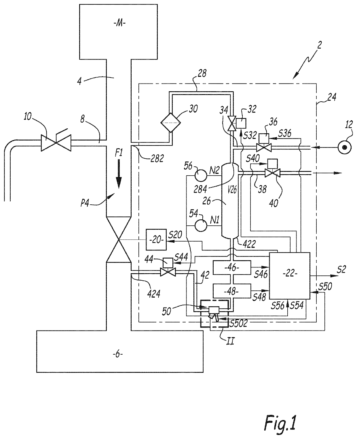
[0128]FIGS. 8 to 11 schematically illustrate the successive steps of an automated process carried out using the installation 2 of FIG. 1. This process is automated inasmuch as it can be implemented, partially or preferably totally, without human intervention, under the control of the unit 22. The same is true for the process explained below regarding the invention.

[0129]By default, and outside withdrawal phases, the oil leaving the equipment M flows in the pipe 4, in the direction of arrow F1 in FIG. 1, from the equipment M toward the oil pan 6, without being retained by the valve 20, which is in the open or on configuration, while the other valves are closed.

[0130]When it is appropriate to determine the iron content of the oil leaving the equipment M, the unit 22 orders the valve 20 to close, such that a retention is created in the pipe 4 where a quantity of oil, i.e., lubricant, accumulates, as shown by the gray part L in FIG. 2.

[0131]In the configuration of FIG. 8, the pipe 4 ser...

first embodiment

[0142]According to another alternative of the invention that is not shown, several pipes comparable to the pipe 4 are used, each of them being provided to collect oil from part of the equipment M. In this case, each of said pipes is equipped with a valve comparable to the valve 20, which allows them to supply, in parallel, a shared buffer tank comparable to the tank 26. Like in the first embodiment, a sensor, identical to the sensor 50, is arranged in a pipe for discharging lubricant from this buffer tank.

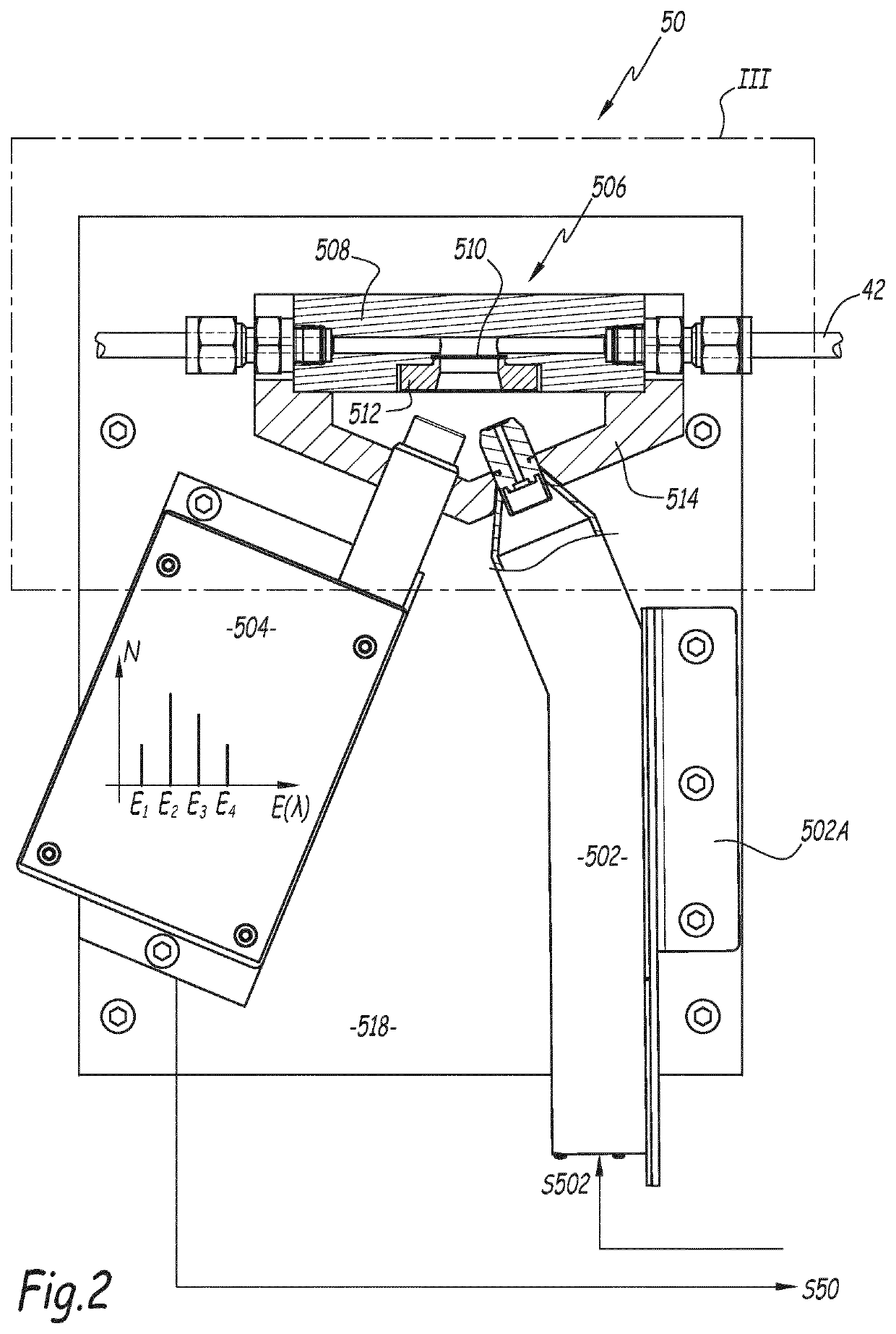
[0143]The invention is described above in the case where the sensor 50 is used to determine the iron content of a lubricant. It is, however, applicable for determining the content of a lubricant in another predetermined chemical element, for example calcium, sulfur, vanadium, chromium, molybdenum, copper, silver, tin, aluminum, nickel, zinc, lead or phosphorus. In all cases, the component material of the casing is suitable for the chemical element in question, as well as the energy...


PUM

PropertyMeasurementUnit
energyaaaaaaaaaa
energyaaaaaaaaaa
thicknessaaaaaaaaaa

Abstract

A sensor for determining the overall content of a pre-determined chemical element in a liquid body uses X-ray fluorescence technology and includes an X-ray source, an X-ray detector, and a cell intended to contain a sample of lubricant to be analyzed, and is provided with a wall forming a window for passage of X-rays, the wall of the sensor cell being produced from polyethylene terephthalate, the cell also including a casing defining an internal volume for receiving the sample. A procedure for calibrating the sensor, and an automated method for online monitoring are also described and claimed.

Description

CROSS-REFERENCE TO RELATED APPLICATIONS[0001]This application claims benefit under 35 USC § 371 of PCT Application No. PCT / EP2017 / 063534 entitled PROCEDURE FOR CALIBRATING A SENSOR, AUTOMATED METHOD FOR ONLINE MONITORING OF THE CHANGES TO A LIQUID BODY AND ASSOCIATED SENSOR, filed on Jun. 2, 2017 by inventors Yann Troadec, Raphael Juston and François Chaudoreille. PCT Application No. PCT / EP2017 / 063534 claims priority of French Patent Application No. 16 55024, filed on Jun. 2, 2016.FIELD OF THE INVENTION[0002]The invention relates to a process for calibrating a sensor for determining the overall content, in a predetermined chemical element, of a liquid body. The invention also relates to an automated method for online monitoring of the changes to the overall content in a predetermined chemical element of a liquid body, which comprises implementing such a calibration process. Lastly, the invention relates to a sensor making it possible to implement this process and this method.[0003]T...

Claims


Application Information

Patent Timeline
Patent Type & Authority Patents(United States)
IPC IPC(8): G01N23/223G01N33/28G01N33/30
CPCG01N33/2888G01N33/30G01N33/2858G01N23/223
Inventor TROADEC, YANNJUSTON, RAPHAËLCHAUDOREILLE, FRANÇOIS
Owner WIKA
Why Eureka
Try Eureka