
Quantum simulator and quantum simulation method

a simulator and quantum simulation technology, applied in the field of quantum simulator and quantum simulation method, can solve the problems of difficulty in building the preferred model which properly shows the characteristic of an object, low “reproduction” degree of structure and distribution, etc., and achieve excellent reproducibility and controllability. excellent

Active Publication Date: 2020-11-03
HAMAMATSU PHOTONICS KK +1
View PDF2 Cites 0 Cited by
  • Summary
  • Abstract
  • Description
  • Claims
  • Application Information

AI Technical Summary

Benefits of technology

The patent aims to provide a quantum simulator and a quantum simulation method that can easily create a preferred model that accurately represents an object. The invention is highly reproducible and controllable, making it a useful tool for researchers to study and model quantum phenomena.

Problems solved by technology

However, even in this technique, only contrast of a speckle pattern is adjusted, and therefore, degree of freedom in setting a spatial structure and a light intensity statistical distribution of a generated speckle pattern and “degree of reproduction” of the structure and the distribution are low.
Accordingly, a conventional quantum simulator which performs optical trap or simulation of an effect of a disordered force field by using a speckle pattern, or a quantum simulation method using the quantum simulator cannot generate a speckle pattern having a desired spatial structure or a light intensity statistical distribution with excellent reproducibility, and for this reason, a preferred model which shows a characteristic of an object properly is difficult to be constructed.

Method used


Image

  • Quantum simulator and quantum simulation method
  • Quantum simulator and quantum simulation method
  • Quantum simulator and quantum simulation method

Examples


first embodiment

[0104]FIG. 11 is a diagram illustrating a configuration of a pseudo speckle pattern generator 1A of the The pseudo speckle pattern generator 1A includes the controller 10, the light source 11, the beam expander 12, and the spatial light modulator 13, and outputs the pseudo speckle pattern b(x, y) on an output plane of the spatial light modulator 13.

[0105]The light source 11 outputs light. For example, a laser light source, a lamp light source, an SLD (superluminescent diode) light source, or the like is used as the light source 11. The beam expander 12 is optically coupled to the light source 11, and outputs the light output from the light source 11 after enlarging a beam diameter. At this time, the light output from the beam expander 12 preferably has an intensity which is uniform in a beam cross section.

[0106]The spatial light modulator 13 is of an intensity modulation type, and has an intensity modulation distribution based on the pseudo speckle pattern b(x, y) generated in step...

fourth embodiment

[0122]FIG. 14 is a diagram illustrating a configuration of a pseudo speckle pattern generator 1D of the The pseudo speckle pattern generator 1D includes the controller 10, the light source 11, the beam expander 12, the spatial light modulator 15, and the lens 16, and generates the pseudo speckle pattern b(x, y) on the light pattern generating plane P.

[0123]The spatial light modulator 15 is of a phase modulation type, and has a phase modulation distribution based on the pseudo speckle pattern b(x, y) generated in step S32 or S61. For the spatial light modulator 15 of a phase modulation type, for example, a modulator using liquid crystal as a modulation medium is used. The spatial light modulator 15 is optically coupled to the beam expander 12, inputs the light which is output from the light source 11 and has a beam diameter enlarged by the beam expander 12, spatially modulates the input light in accordance with the modulation distribution, and outputs the modulated light. The lens 1...


PUM


Abstract

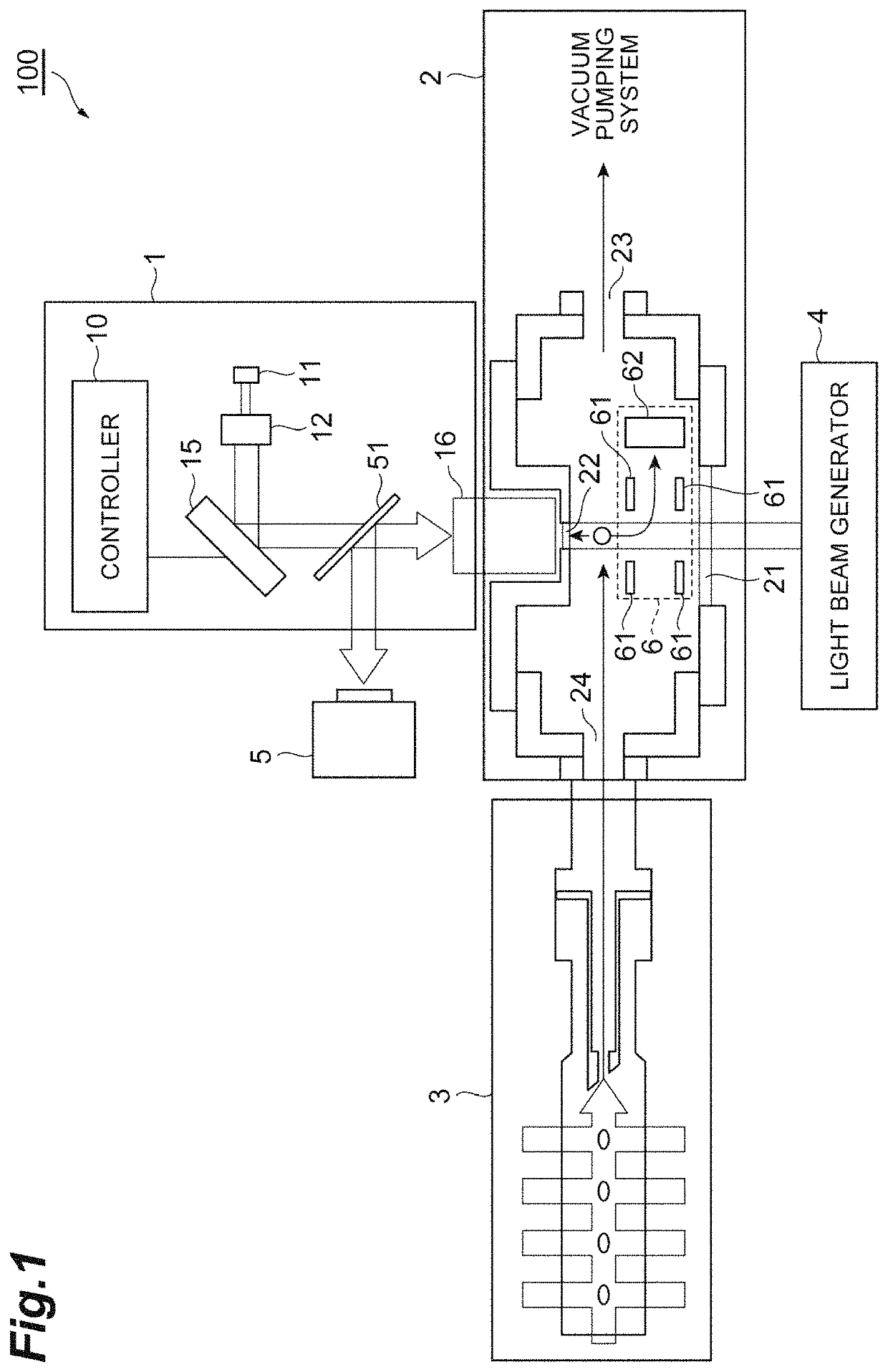
A quantum simulator includes a pseudo speckle pattern generator, a main vacuum chamber, an atomic gas supply unit, a light beam generator, a photodetector, and an atom number detector. The pseudo speckle pattern generator generates a pseudo speckle pattern in the inside of the main vacuum chamber by light allowed to enter the inside of the main vacuum chamber through the second window. The pseudo speckle pattern generator includes a controller, a light source, a beam expander, a spatial light modulator, and a lens. The controller sets a modulation distribution of the spatial light modultor based on a two-dimensional pseudo random number pattern.

Description

BACKGROUND OF THE INVENTIONField of the Invention[0001]The present disclosure relates to a quantum simulator and a quantum simulation method.Related Background Art[0002]The behavior of a substance in a micro region of atomic level has been known to obey quantum mechanics. A phenomenon in such a micro region has a length scale which is significantly different from a scale of the real world, and does not usually appear in a form which is directly visible to us. However, due to the development of a science and technology in recent years, an effective technique which uses quantum mechanical effects has begun to be produced. The range of applications of the technique extends widely, such as superconductivity, a communication element, development of a medicine, and a substance with a new function (such as a special electric conductive substance, and a strong magnet), and accordingly, understanding the behavior of quanta is becoming important as a first step of producing a new technique.[0...

Claims


Application Information

Patent Timeline
Patent Type & Authority Patents(United States)
IPC IPC(8): G03H1/08G03H1/00G03H1/22H05H3/00G03H1/16G03H1/04G21K1/00
CPCG03H1/0443G21K1/006G03H1/2294H05H3/00G03H1/0808G03H1/16G03H1/0005G03H2210/55G03H2225/30G03H2001/0441
Inventor SAKAI, HIROTOOHMORI, KENJIANDO, TAROTAKEI, NOBUYUKITOYODA, HARUYOSHIOHTAKE, YOSHIYUKIHYODO, TOMOKOTAKIGUCHI, YUU
Owner HAMAMATSU PHOTONICS KK
Learn More