Supercharge Your Innovation With Domain-Expert AI Agents!

Honeycomb filter

a filter and honeycomb technology, applied in the field of honeycomb filters, can solve the problems of difficult flow of exhaust gas and increase of pressure loss of honeycomb filters, and achieve the effects of reducing pressure loss, reducing pressure loss, and effectively suppressing an increase in pressure loss

Active Publication Date: 2021-02-16
NGK INSULATORS LTD
View PDF15 Cites 2 Cited by
  • Summary
  • Abstract
  • Description
  • Claims
  • Application Information

AI Technical Summary

Benefits of technology

The present invention provides a honeycomb filter that can achieve low pressure loss when in use. The filter is designed to suppress an increase in pressure loss attributable to the accumulation of PM on the surfaces of partition walls. The filter has a relatively larger thickness of the second partition walls, which increases the volume of the pores in the walls and achieves a smooth flow of exhaust gas. This results in a low pressure loss of the filter. The first partition walls tend to accumulate PM, leading to an increase in permeation resistance, but the second partition walls can be used effectively as the through channels of exhaust gas. The second partition walls contribute less to an increase in pressure loss in an initial state of use. The present invention provides a honeycomb filter with these technical features to achieve a low pressure loss and efficient filtration of exhaust gas.

Problems solved by technology

In the conventional honeycomb filters described in Patent Documents 1 to 7, there has been a tendency in that the permeation resistance of “the partition walls provided between the inflow cells” is higher than that of “the partition walls provided between inflow cells and outflow cells”, thus making it difficult for exhaust gas to flow.
For this reason, the conventional honeycomb filters have been posing a problem of uneven flow of exhaust gas in the honeycomb filters, leading to an increase in the pressure loss of the honeycomb filters.

Method used


Image

  • Honeycomb filter
  • Honeycomb filter
  • Honeycomb filter

Examples


example 1

[0103]First, the kneaded material for producing a honeycomb substrate was prepared. In Example 1, as the raw material powder for preparing the kneaded material, a powder mixture was prepared by mixing silicon carbide (SiC) powder and silicon metal (Si) powder at a mass ratio of 80:20. A binder, a pore former, and water were added to the powder mixture to make the forming raw material. Then, the forming raw material was kneaded to produce a round pillar-shaped kneaded material.

[0104]Subsequently, the kneaded material was extruded by using a die for fabricating a honeycomb formed body, thereby obtaining a honeycomb formed body that has a round pillar-shaped overall shape.

[0105]Subsequently, the honeycomb formed body was dried by a microwave drier, and further dried by a hot air drier until completely dried. Then, both end faces of the honeycomb formed body were cut to predetermined dimensions.

[0106]Subsequently, plugging portions were formed on the dried honeycomb formed body. More sp...

example 13

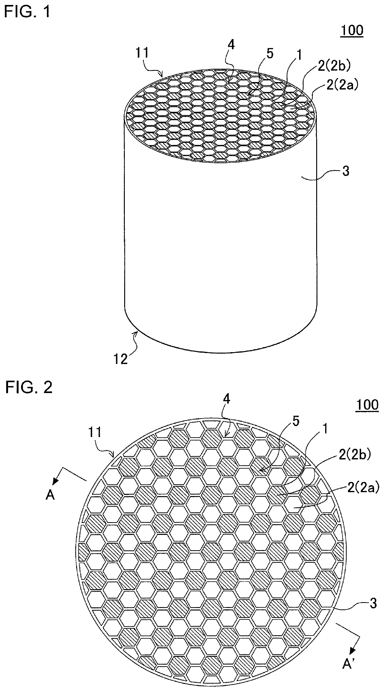
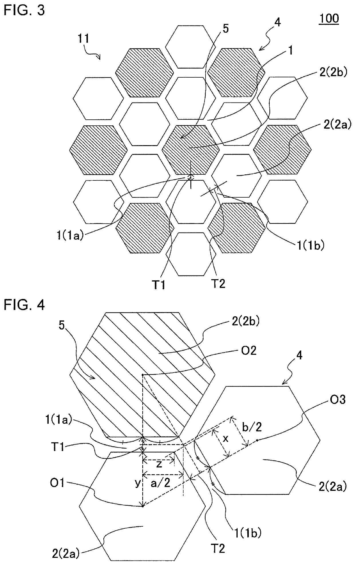
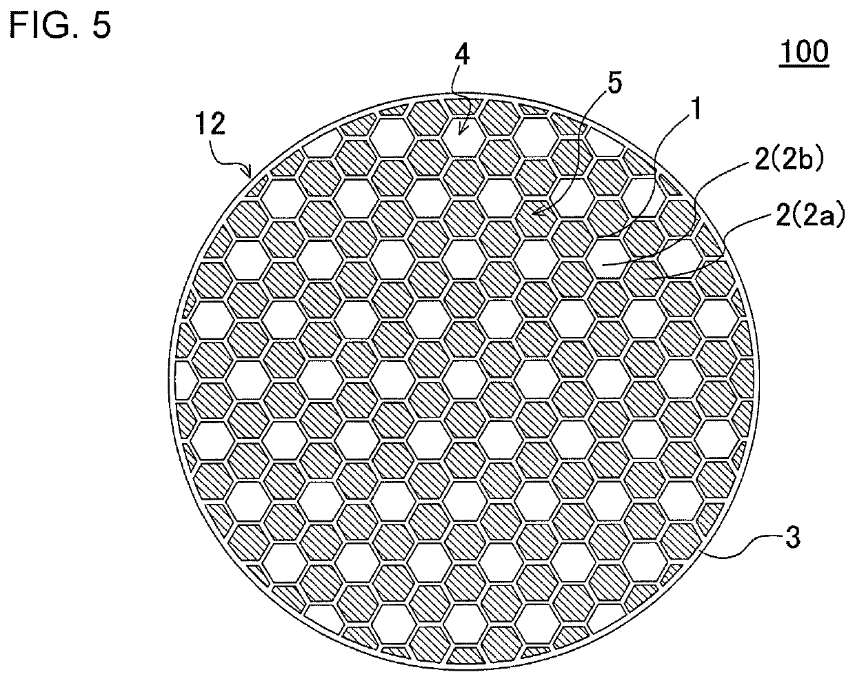
[0126]For Example 13, the kneaded material prepared according to the same method as that for the kneaded material prepared for Example 1 was used to produce the honeycomb filter having the cell structure shown in FIG. 2 and FIG. 3. More specifically, the inflow cells 2a of the honeycomb filter of Example 13 had a regular hexagonal shape and the outflow cells 2b also had a regular hexagonal shape, as with the honeycomb filter 100 shown in FIG. 2 and FIG. 3. Further, the honeycomb filter of Example 13 had a cell structure in which six regular hexagonal inflow cells 2a were arranged to surround the periphery of the outflow cell 2b having the regular hexagonal shape, as shown in FIG. 2 and FIG. 3.

[0127]The porosity of the partition walls of the honeycomb filter of Example 13 was 41%. The diameter of the end faces was 266.7 mm, and the length in the extending direction of the cells was 254.0 mm. The porosities of the partition walls are denoted by the values measured by a mercury porosim...


PUM

PropertyMeasurementUnit
thickness T1aaaaaaaaaa
lengthaaaaaaaaaa
porosityaaaaaaaaaa

Abstract

A honeycomb filter includes a pillar-shaped honeycomb substrate and a plugging portion provided at an end portion on either an inflow or outflow end face side of cells, wherein, in a section orthogonal to the cell extending direction, the shapes of an inflow cell having the plugging portion and an outflow cell having the plugging portion are hexagonal. In the plurality of cells, a plurality of inflow cells surround one outflow cell such that one side of the inflow cell and one side of the outflow cell adjacent to the inflow cell are parallel. The partition wall includes a first partition wall and a second partition wall, at least one of the first partition walls is configured such that a ratio of a thickness of the second partition wall to the first partition wall is 1.0 to 2.5, and a total open frontal area is 35% to 95%.

Description

[0001]The present application is an application based on JP 2018-181616 filed on Sep. 27, 2018 with Japan Patent Office, the entire contents of which are incorporated herein by reference.BACKGROUND OF THE INVENTIONField of the Invention[0002]The present invention relates to a honeycomb filter, and more particularly, to a honeycomb filter capable of achieving a low pressure loss when in use.Description of the Related Art[0003]In various industries, internal-combustion engines are used as power sources. On the other hand, the exhaust gas emitted when an internal-combustion engine burns a fuel contains poisonous gases, such as nitrogen oxides, and particulate matters, such as soot or ash. Hereinafter, the particulate matters may be referred to as “PM.” The “PM” stands for particulate matters. In recent years, the regulations on the removal of PM discharged from diesel engines are becoming increasingly strict worldwide, and as the filters for removing PM, a wall flow type filter having ...

Claims


Application Information

Patent Timeline
Patent Type & Authority Patents(United States)
IPC IPC(8): B01D46/24
CPCB01D46/2474B01D46/247B01D46/2429B01D2046/2433B01D2046/2492B01D46/2418F01N3/022B01D46/2492B01D46/2484B01D46/2482B01D46/2455B01D46/24491B01D46/2476
Inventor MAKINO, TETSUYATERANISHI, MAKOTOITO, TADATOOHARA, ETSUJI
Owner NGK INSULATORS LTD
Features
  • R&D
  • Intellectual Property
  • Life Sciences
  • Materials
  • Tech Scout
  • Unparalleled Data Quality
  • Higher Quality Content
  • 60% Fewer Hallucinations
Learn More