
Nanofiber coating to improve biological and mechanical performance of joint prosthesis

a technology of nanofibers and prosthesis, applied in the field of polymer fiber production, can solve the problems of coating detachment and toxicity of related debris, and achieve the effects of improving osseointegration, enhancing osteoinductive properties, and increasing osseointegration

Active Publication Date: 2021-03-02
UNIVERSITY OF CENTRAL OKLAHOMA
View PDF114 Cites 0 Cited by
  • Summary
  • Abstract
  • Description
  • Claims
  • Application Information

AI Technical Summary

Benefits of technology

[0010]The process of the present invention provides methods to achieve adhesion of functional nanofiber coatings on a biomedical implant surface to increase the osteoinductive properties, and thereby to improve osseointegration of implant. The effects of fibers on the mechanical stability and osseointegration of an implant with and without fibers have not previously been known. In one aspect, a specific objective of the present invention is to provide methods to attach ENF fibers to an implant surface. Another objective of the present invention is to increase osseointegration at the tissue-cement interface by improving the bioactivity of cement using biocompatibility nanofiber membrane (NFM). Yet another objective of the present invention is to provide the means to apply nanofiber membrane (NFM) coating on implant surfaces for total cementless hip and knee replacement surgeries to improve the implant osseointegration. The methods provided by the present invention can be used for both regular and irregular shape implants, including implants used in shoulder replacement surgery.

Problems solved by technology

The main concern related to coating nanoscale materials onto an implant surface is the risk of coating detachment and toxicity of related debris.

Method used


Image

  • Nanofiber coating to improve biological and mechanical performance of joint prosthesis
  • Nanofiber coating to improve biological and mechanical performance of joint prosthesis
  • Nanofiber coating to improve biological and mechanical performance of joint prosthesis

Examples


Embodiment Construction

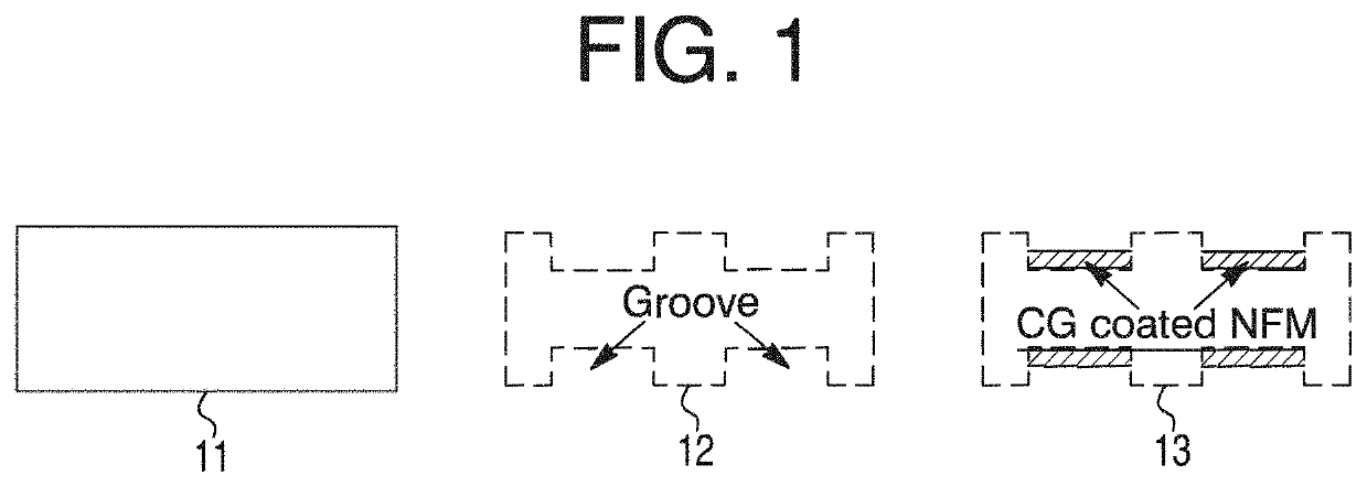
"d_n">[0065]Referring now to FIG. 1, a non-limiting diagram shows schematic images of a longitudinal cross-section of a Ti rod without grooves 11, with circumferential grooves 12, and with circumferential grooves and nanofiber matrix (NFM) applied 13. The process of the present invention provides a method for controlled fabrication of microgrooves 12 around the circumference of a Ti implant 11. The present invention provides techniques to attach ENF fibers to an implant surface as shown positioned within the groves 13.

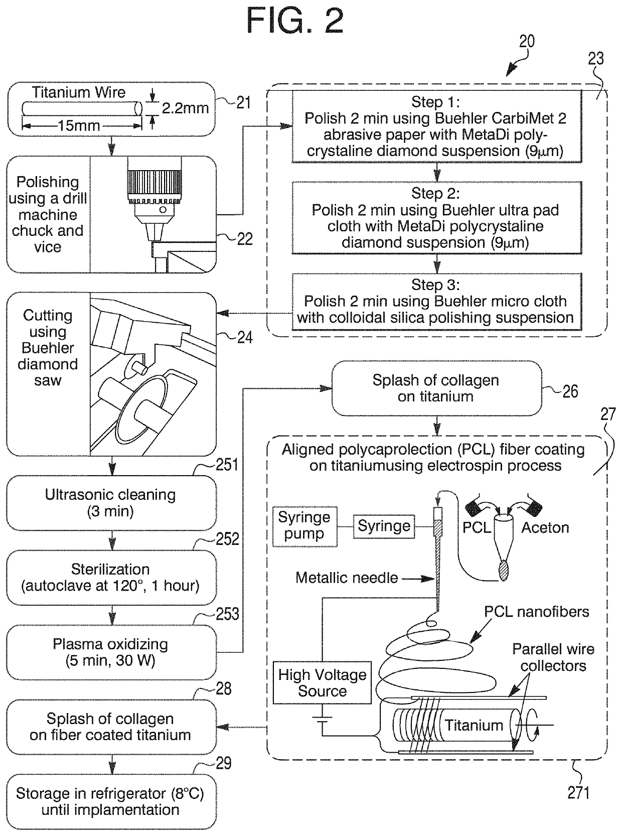
[0066]Referring now to FIG. 2, a non-limiting diagram shows the process of the present invention providing a method 20 for coating a metal implant with electrospun nanofiber, and includes a set of steps (shown in block diagram) by which PCL ENF can be bonded with the metal implant [See FIG. 8, 83]. Briefly, a Ti implant 21 (e.g., 2.2 mm×15 mm wire) may be polished using a drill machine chuck and gripper 22. Other functionally equivalent rotating devices may be used. A ...


PUM

PropertyMeasurementUnit
thicknessaaaaaaaaaa
depthaaaaaaaaaa
thicknessaaaaaaaaaa

Abstract

The present invention provides a process to functionalize nanofiber membrane (NFM) on a total joint replacement (TJR) implant surface to support bone ingrowth and reduce macrophage-associated inflammation, the process comprising amending the implant surface by laser cutting microgrooves greater than 100 μm in depth to protect functional PCL NFM from applied loading, induce a higher amount of osteoblast cell function, increase implant-bone contact area, and serve as a reservoir for the local delivery of biomolecules to increase osseointegration of the implant; depositing aligned fibers on the implant surface, the fibers aligned in the direction of the microgrooves and collected in layers until a thickness less than 30 μm is reached and preferably in the range of 1 μm to 10 μm. Biofunctionalized NFM are used to indirectly attach biomolecules on said implant surface, or extracellular matrix proteins with biomolecules are immobilized and deposited on the PCL NFM coated implant.

Description

CROSS REFERENCES TO RELATED APPLICATIONS[0001]This application is a continuation-in-part of U.S. patent application Ser. No. 15 / 791,571 filed Oct. 24, 2017 by the University of Central Oklahoma (Applicant), entitled “Method and apparatus to coat a metal implant with electrospun nanofiber matrix” the entire disclosure of which is incorporated herein by reference in its entirety for all purposes; which application is a continuation of U.S. patent application Ser. No. 15 / 467,652 filed Mar. 23, 2017 by the University of Central Oklahoma (Applicant) and now U.S. Pat. No. 9,809,906 issued Nov. 7, 2017, entitled “Method and apparatus to coat a metal implant with electrospun nanofiber matrix” the entire disclosure of which is incorporated herein by reference in its entirety for all purposes; which application claims the benefit of U.S. Provisional Patent Application No. 62 / 312,041 filed on Mar. 23, 2016 in the name of Morshed Khandaker and Shahram Riahinezhad, which is expressly incorporate...

Claims


Application Information

Patent Timeline
Patent Type & Authority Patents(United States)
IPC IPC(8): A61F2/28A61F2/30D01D5/00D01F6/62A61F2/36A61F2/38D01F1/10
CPCA61F2/28A61F2/30771A61F2/36A61F2/38D01D5/0007D01D5/0084D01F6/625A61F2002/2817A61F2002/3082A61F2002/3084A61F2002/30677A61F2002/30838A61F2002/30909A61F2310/00023D01F1/10D10B2331/041D10B2509/00
Inventor KHANDAKER, MORSHEDRIAHINEZHAD, SHAHRAMSNOW, WILLIAM PAUL
Owner UNIVERSITY OF CENTRAL OKLAHOMA
Learn More