Method for operating a multi-frequency metal detector and multi-frequency metal detector

a multi-frequency metal detector and metal detector technology, applied in the direction of instruments, measurement devices, electrically powered circuit arrangements, etc., can solve the problems of large cost, large number of relatively high energy harmonics, and inability to achieve the desired results of other metal contaminants at the same frequency, so as to achieve the effect of reducing cost, improving efficiency, and being constructively simpl

Active Publication Date: 2021-04-27
METTLER TOLEDO SAFELINE LTD
View PDF10 Cites 0 Cited by
  • Summary
  • Abstract
  • Description
  • Claims
  • Application Information

AI Technical Summary

Benefits of technology

[0015]The metal detector shall be equipped with an improved multi-frequency transmitter that has improved efficiency, is constructively simple, can be built at reduced cost and allows maximizing the coil current delivered to the drive coil.
[0016]The inventive method and metal detector shall allow producing high drive currents in the drive coil, while currents in the transmitter unit remain comparably low so that the transmitter circuitry can be dimensioned accordingly, e.g. with reduced power performance and cost.
[0028]The drive switches are actuated by means of the predetermined PXM-signal or by two or more PXM signals. In the event that only one PXM-signal is provided, then this PXM signal is applied to the drive switches directly or via inverters, so that the individual drive switches are actuated correctly. In the event that two PXM signals are provided, the drive circuitry, which preferably comprises amplifiers, can get simplified.
[0036]The drive current can directly be supplied to the drive coil so that's the drive current provided by the converter and the coil current delivered to the drive coil are identical. In a preferred embodiment however, the drive current it is supplied via an admittance unit to the drive coil, which admittance unit together with the drive coil forms resonant circuits that are active in the two or more different frequency components of the drive current. By tuning the resonant circuits of the admittance unit and the drive coil to the frequency components of the drive current or vice versa the current appearing in the drive coil will be significantly larger than the drive current flowing through the drive switches or power FETs. The multi-frequency transmitter unit with the power FETs can therefore be dimensioned for smaller currents than actually required in the drive coil. Furthermore when the output impedance of the converter is high by properly tuning the resonant circuits, the level of the frequency components desired for detecting contaminants in the products is increased, while other unwanted frequency components are not increased or even reduced, thus improving the signal-to-noise ratio of the obtained signals and the sensitivity of the metal detector.
[0039]The implementation of the method and devices for creating the multi-frequency drive current on the one hand and the use of the admittance unit on the other hand are particularly advantageous when implemented in combination but also provide significant improvements, when implemented independently from one another. I.e., the inventive admittance unit which forms together with the drive coil two or more individually tuned resonant circuits can also advantageously be applied in metal detectors, in which the multi-frequency drive current these obtained according to another method.

Problems solved by technology

However, driving the coil system by a square wave (or a trapezoidal wave due to the inductance of the coil) generates a large number of relatively high energy harmonics compared with the conventional sinusoidal signal generated by a tuned circuit.
While one operating frequency may be suitable for one specific metal contaminant, the same frequency may not provide the desired results for other metal contaminants.
The multi-frequency transmitter must therefore be dimensioned and built accordingly with considerable costs.

Method used


Image

  • Method for operating a multi-frequency metal detector and multi-frequency metal detector
  • Method for operating a multi-frequency metal detector and multi-frequency metal detector
  • Method for operating a multi-frequency metal detector and multi-frequency metal detector

Examples


Embodiment Construction

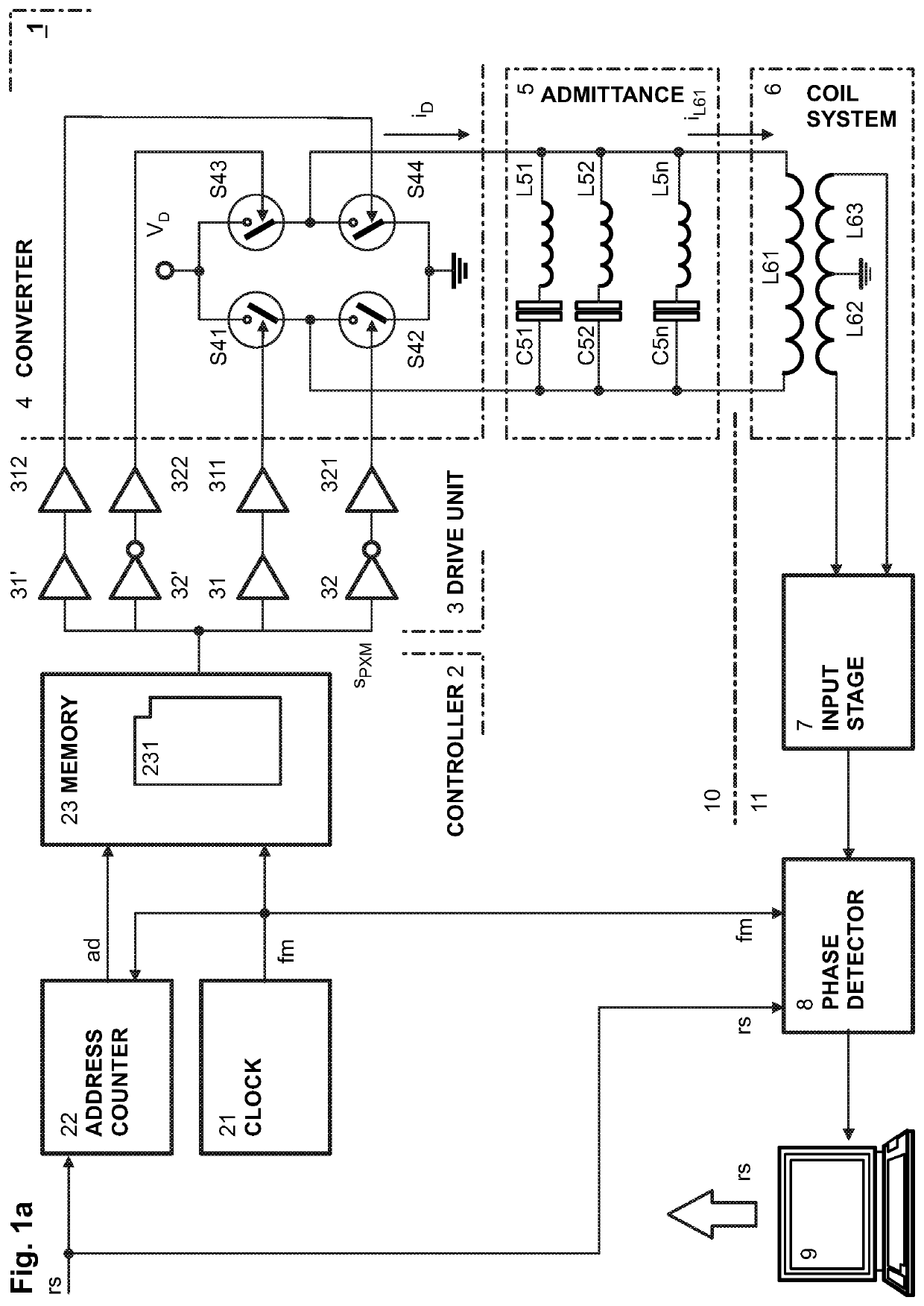
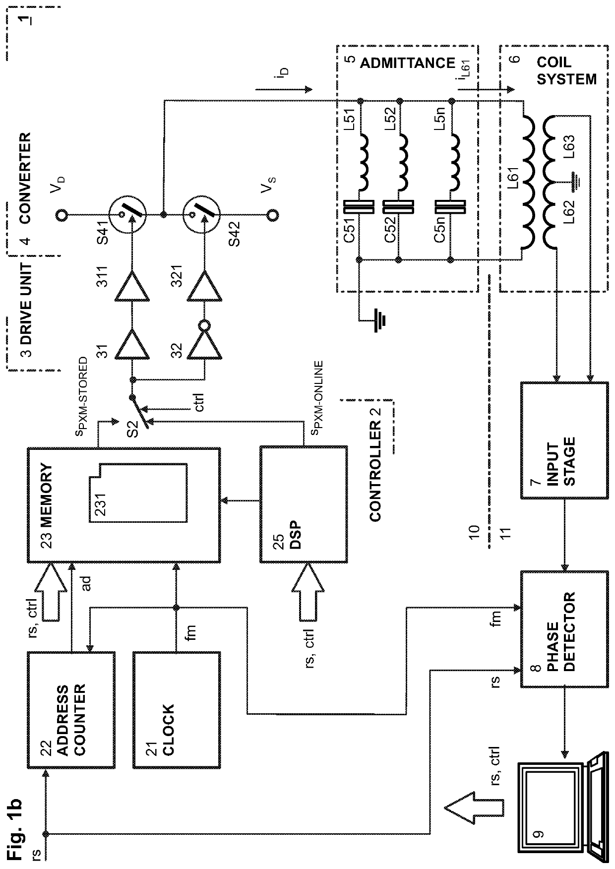
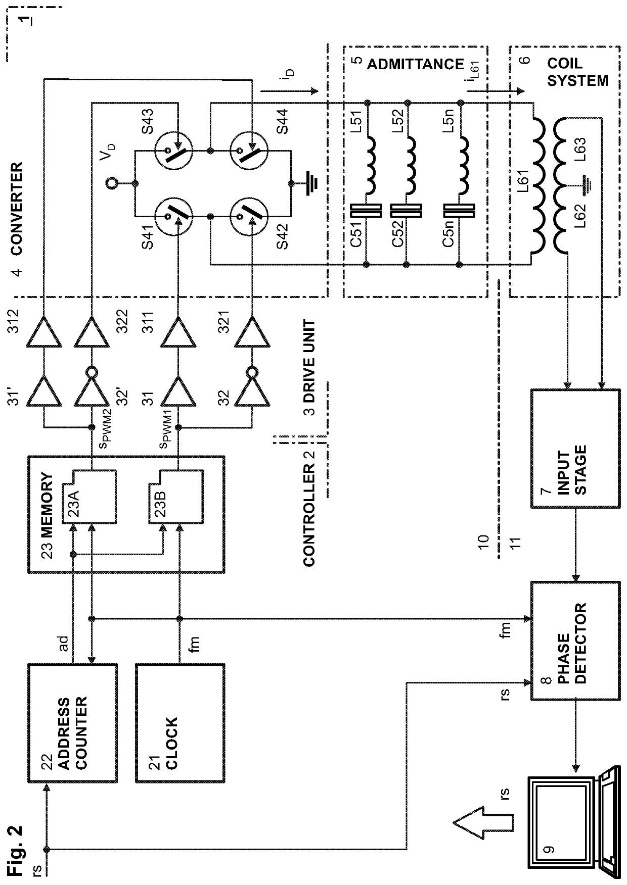
[0047]FIG. 1a shows a first embodiment of an inventive metal detector 1 that comprises a transmitter unit 10 and a receiver unit 11 and a balanced coil system 6 with a drive coil L61 connected to the output of the transmitter unit 10 and two detection coils L62 and L63 connected on one end to ground potential and with the other end to an input stage 7 of the receiver unit 11. In the input stage 7 the input signal is typically amplified and filtered and then forwarded to a phase detector 8. The phase detector 8 allows distinguishing between the phases of the signal components of different origin and obtaining information about the observed product and contaminants, if present. A typical phase detector, e.g. a frequency mixer or analogue multiplier circuit, generates two independent voltage signals which represent the in-phase and quadrature component provided by the input stage 7, and a reference signal fm provided by the transmitter unit 10. The output signal of the phase detector 8...


PUM

PropertyMeasurementUnit
operating frequencyaaaaaaaaaa
electromagnetic fieldaaaaaaaaaa
magnetic fieldaaaaaaaaaa

Abstract

A metal detector (1) has a drive coil (L61) and at least one detection coil (L62, L63) that detect fluctuations in a magnetic field generated by the drive coil, caused by metallic particles present in an inspected object. A multi-frequency transmitter unit (10) has a converter (4) with a plurality of drive switches (S41, S42; S43, S44) driven by a drive controller (2). The drive switches alternately conduct a drive current through the drive coil to generate an electromagnetic field with two or more different frequency components. A waveform of the drive current is determined, as is at least one pulse-modulated (PXM) signal corresponding to the determined waveform. The determined PXM-signal is determined online or is stored in a memory module (231; 232). The determined PXM-signal is generated and applied to control the drive switches. The drive current can be applied to the drive coil through an admittance unit (5).

Description

CROSS-REFERENCE TO RELATED APPLICATIONS[0001]This application claims priority to European Patent Application 18154719.1, filed on 1 Feb. 2018, which is incorporated by reference as if fully recited herein.TECHNICAL FIELD[0002]The invention relates to a method for operating a multi-frequency metal detector and to a multi-frequency metal detector operating according to this method.BACKGROUND ART[0003]As described in US published application 2012 / 0206138 A1, metal detectors are used to detect and reject unwanted metal contamination. When properly installed and operated, a metal detector will help reduce metal contamination and improving food safety. Most modern metal detectors utilise a search head comprising a coil system with a drive coil receiving a drive signal and generating an electromagnetic field in the product, and at least one detection coil arranged to detect fluctuations in the magnetic field caused by the presence of metallic particles in the product including ferrous, non...

Claims


Application Information

Patent Timeline
Patent Type & Authority Patents(United States)
IPC IPC(8): G01V3/10H01F7/06
CPCG01V3/10G01V3/107H01F7/064
Inventor TAO, YANGKTISTIS, CHRISTOS
Owner METTLER TOLEDO SAFELINE LTD
Why Eureka
Try Eureka