
Stimulated X-ray emission source with crystalline resonance cavity

Active Publication Date: 2021-05-04
BRUKER AXS
View PDF5 Cites 0 Cited by
  • Summary
  • Abstract
  • Description
  • Claims
  • Application Information

AI Technical Summary

Benefits of technology

The present invention is for an X-ray laser that uses a crystal to produce X-ray beams. The laser includes an X-ray source that generates an input X-ray beam and an electron source that causes electrons to impact the crystal, resulting in X-ray emission. The input X-ray beam is directed at the crystal at a specific angle and can have low angular divergence. The X-ray beam can be collimated and directed to the same surface as the incident electron beam. The target anode and substrate can be cooled to minimize temperature gradients. The technical effect is that the invention provides a reliable and efficient way to produce high-quality X-ray beams.

Problems solved by technology

However, the current generation of free electron lasers are found primarily in expensive national facilities, and more affordable options are generally unavailable.
In practice, however, due to an inefficient ionization process, it is possible to operate such a laser only in a single-pulse mode, which is not particularly useful for laboratory diffraction experiments.
However, due to the excess heat generated, an ionization rate sufficient to attain a steady state population inversion would also be so high as to thermally destroy the crystal.
However, the total X-ray flux produced by the tube was not measurably higher than a conventional X-ray tube.

Method used


Image

  • Stimulated X-ray emission source with crystalline resonance cavity
  • Stimulated X-ray emission source with crystalline resonance cavity
  • Stimulated X-ray emission source with crystalline resonance cavity

Examples


Embodiment Construction

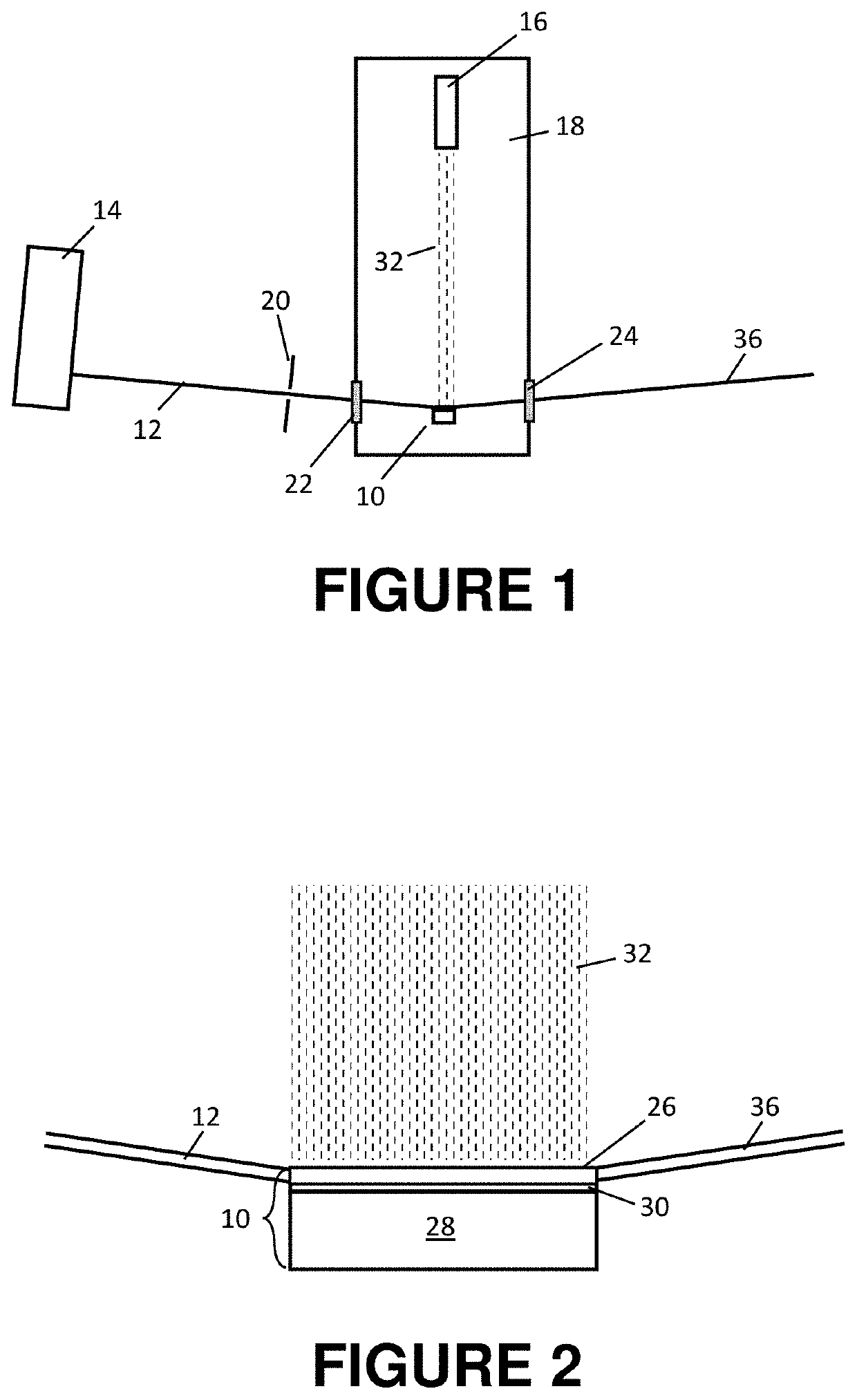
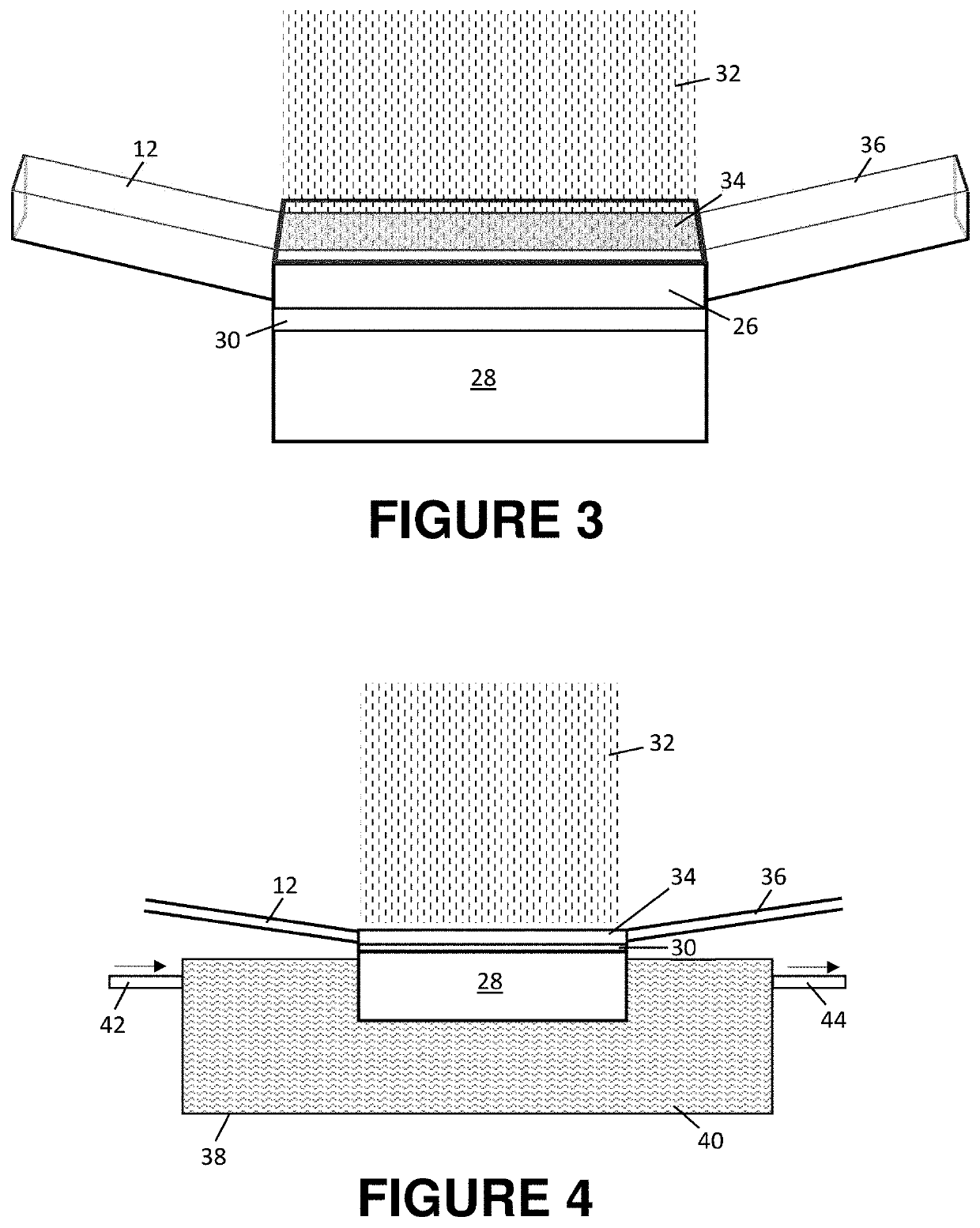
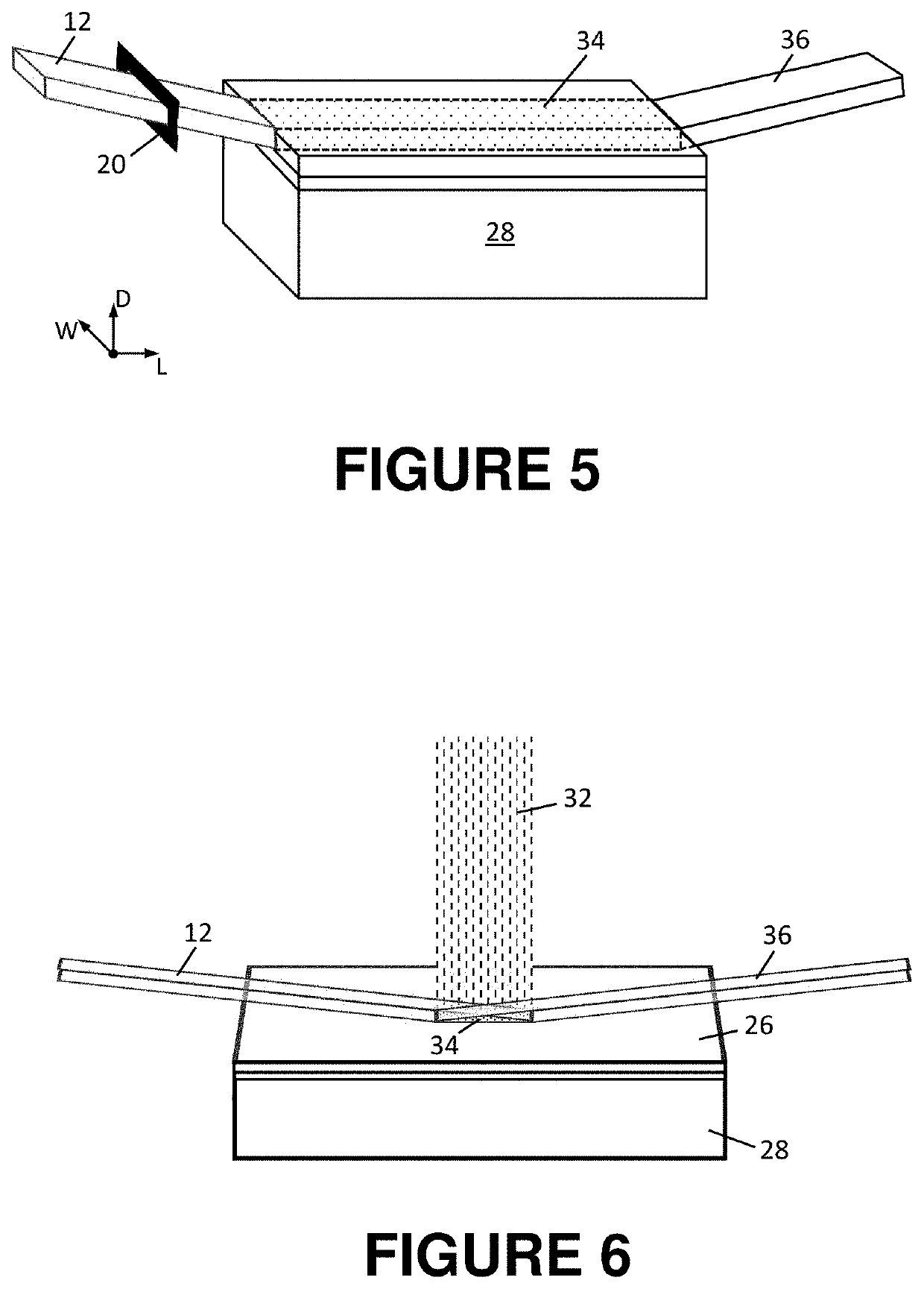
[0017]Shown in FIG. 1 is a cross-sectional schematic view of an X-ray emission source according to the present invention. The source relies on stimulated emission of coherent X-ray radiation from an anode structure 10 having a crystalline target anode. In the exemplary embodiment, the anode is copper (Cu), molybdenum (Mo) or Silver (Ag), as the emission wavelengths from these materials are commonly used in X-ray applications, but those skilled in the art will understand that other crystalline materials may be used as well.

[0018]An X-ray beam 12 is directed onto the anode from a microfocus X-ray tube 14 (also referred to as the “drive tube”). The drive tube is chosen such that the anode material in the drive tube is the same as that of target anode material, so as to provide wavelength matching between the kα radiation of the drive tube and the emission modes of the anode target. The interaction of the X-ray beam 12 with the anode induces an X-ray standing wave, known as the Borrmann...


PUM


Abstract

An X-ray laser has a target anode of a crystalline material that emits X-ray radiation in response to excitation and that is located on a thermally conductive substrate. An X-ray source provides an input X-ray beam that illuminates a predetermined volume of the target anode at a predefined angle relative to a surface of the anode so as to induce a Borrmann mode standing wave in the predetermined volume. An electron source outputs an electron beam that is incident on the Borrmann mode region so as to cause electron impact ionization of the crystalline material and thereby induce stimulated emission of a coherent output X-ray beam.

Description

BACKGROUND OF THE INVENTIONField of the Invention[0001]This invention relates generally to the field of X-ray emission sources and, more particularly, to a highly-brilliant X-ray laser.Description of the Related Art[0002]Single crystal X-ray diffraction or crystallography requires a highly brilliant, highly monochromatic and well collimated (non-divergent) source. It is well-understood in the prior art that an X-ray laser fulfills these requirements better than most available sources. Indeed, free electron lasers are currently the most brilliant sources of X-rays available (see, e.g., B. Patterson, Crystallography using Free Electron Lasers, Crystallography Reviews, 20, 2014, 242-294). However, the current generation of free electron lasers are found primarily in expensive national facilities, and more affordable options are generally unavailable.[0003]One prior art version of an X-ray laser is described in U.S. Pat. No. 3,967,213 to Yariv. Therein, Yariv describes a concept in whic...

Claims


Application Information

Patent Timeline
IPC IPC(8): H01S3/30H01S4/00H01S3/0959
CPCH01S4/00H01S3/0959H05G2/00
Inventor DURST, ROGER D.GRAF, JUERGENOLLINGER, CHRISTOPH
Owner BRUKER AXS
Learn More