Method for embossing micro-structures and/or nano-structures
Active Publication Date: 2021-06-22
EV GRP E THALLNER GMBH
View PDF8 Cites 0 Cited by
- Summary
- Abstract
- Description
- Claims
- Application Information
AI Technical Summary
Benefits of technology
The present invention aims to provide a method and device that overcome the shortcomings of existing technology. Specifically, it is designed to improve dimensional accuracy and reduce maintenance efforts.
Problems solved by technology
However, it is possible not to structure the embossing roll itself, and in particular to bring a structured layer (for example for example embossing structures on and / or in an underlay) and the embossing compound into contact.
The technical parameters of the structure sizes represent a limit to cost effectiveness.
Although precise structures can be created in a first print with an embossing roll, the production of disparate, high-precision structure whose typical sizes differ from each other by several orders of magnitude is often not possible with a roller.
The thermally adverse position of the UV station in the embossing roll or beside the embossing roll is detrimental to the dimensional accuracy of both the embossing compound and the carrier film, accordingly it is not possible to attain steady thermal states, the unevenness of the heating causes further distortions in the embossing roll and / or in the embossing film.
This leads to distortions in the embossed structures, in summary reduced dimensional accuracy.
The effort associated with maintaining the radiation source is also greater if the embossing roll is disassembled for this.
Method used
View moreImage
Smart ImageViewing Examples
Examples
first embodiment
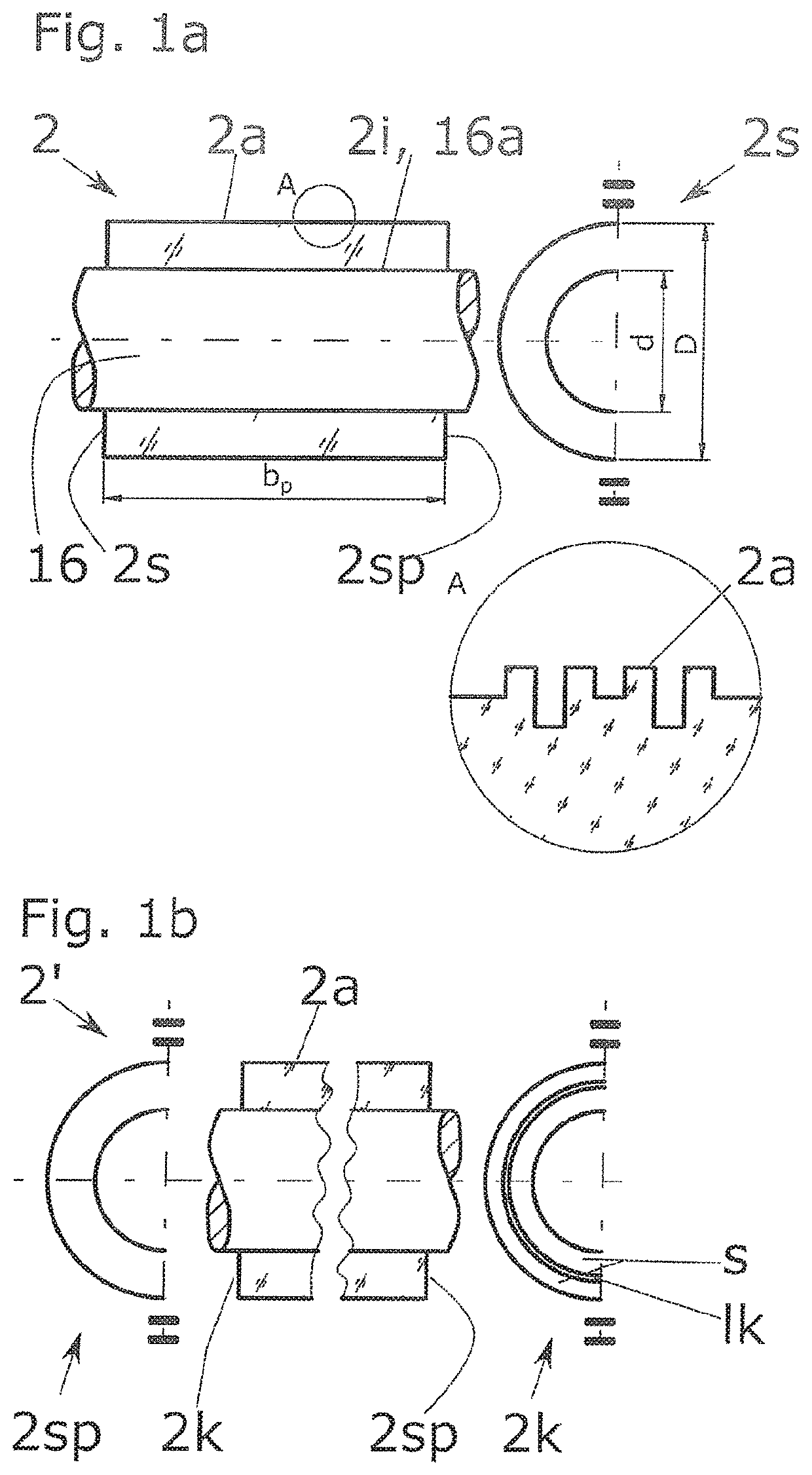
[0095]FIG. 1a is a schematic representation of an embossing roll according to the invention,
second embodiment
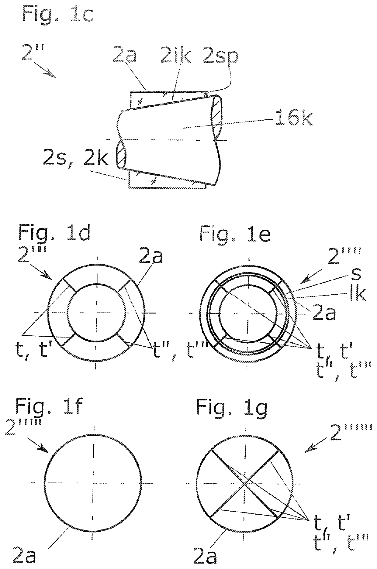
[0096]FIG. 1b is a schematic representation of an embossing roll according to the invention,
third embodiment
[0097]FIG. 1c is a schematic representation of an embossing roll according to the invention,
Login to View More PUM
 Abstract
A method and apparatus for embossing micro-structures and / or nano-structures. The method includes the steps of providing a structured embossing roll having end faces; coupling a crosslinking radiation into the structured embossing roll which is transparent for the crosslinking radiation, wherein the embossing roll functions as a light guide for the coupled in crosslinking radiation; providing a carrier having an embossing compound applied thereto; contacting the embossing roll with the embossing compound; coupling the crosslinking radiation out of the embossing roll; and curing the embossing compound which has been acted upon by the coupled out crosslinking radiation via the embossing roll.
Description
FIELD OF THE INVENTION[0001]The present invention relates to a method and apparatus for embossing micro-structures and / or nano-structures.BACKGROUND OF THE INVENTION[0002]A number of different technologies are already known for producing printed strips and films. These have their origins in traditional offset printing, particularly in web offset printing. The medium to be printed, such as paper or film is drawn off from a supply reel, printed continuously with corresponding with print rollers, and rolled up on a receiver reel. Other parts such as tensioning rollers, deflection rollers, drying rollers or coating rollers may be present in the printing press.[0003]A modified form of web offset printing is used in the semiconductor industry for embossing particularly micro- and / or nanostructures on corresponding carriers.[0004]An embossing compound is applied to a carrier, particularly a carrier film, particularly by spraying, laminating or immersion. The embossing compound is processed...
Claims
Login to View More Application Information
Patent Timeline
 IPC IPC(8): B41F19/02G03F7/00B82Y40/00
CPCB41F19/02B82Y40/00G03F7/0002G03F7/0017G03F7/168G03F7/70033
Inventor KROL, JOZSEFPOVAZAY, BORIS
Owner EV GRP E THALLNER GMBH
Features
- R&D
- Intellectual Property
- Life Sciences
- Materials
- Tech Scout
- Unparalleled Data Quality
- Higher Quality Content
- 60% Fewer Hallucinations
Learn More Browse by: Latest US Patents, China's latest patents, Technical Efficacy Thesaurus, Application Domain, Technology Topic, Popular Technical Reports.
© 2025 PatSnap. All rights reserved.Legal|Privacy policy|Modern Slavery Act Transparency Statement|Sitemap|About US| Contact US: help@patsnap.com


