Guidewire having a fiber optic force sensor with a mirror having a patterned reflectance

a fiber optic force sensor and fiber optic technology, applied in the field of medical devices, can solve the problems of lack of tactile perception, limb impairment, heart failure, etc., and achieve the effects of reducing the risk of damaging vasculature tissue, reducing contrast fluid and x-ray use, and speeding up medical procedures

Active Publication Date: 2021-08-10
LAKE REGION MFG
View PDF6 Cites 3 Cited by
  • Summary
  • Abstract
  • Description
  • Claims
  • Application Information

AI Technical Summary

Benefits of technology

[0010]However, according to the present invention, the mirror is provided with a patterned reflectance that varies along a radius from a central area of reflectance. The patterned reflectance of the mirror means that triangulation can be performed with greater accuracy and that the position of the atraumatic head in an x, y, z coordinate system can be determined with the optical fiber having a single fiber core. A single fiber core does not normally lend itself to triangulation.
[0020]If desired, the controller also uses the force data at the atraumatic head to generate an input signal to an electromechanical vibrator integrated into the guidewire's optical connector so that the surgeon receives force feedback at the hand. This increased feedback to the surgeon helps reduce the risk of damaging vasculature tissue, speeds up medical procedures and reduces contrast fluid and x-ray use. Also, the force data correlates with the hardness of tissue encountered by the guidewire so that the occlusion orientation can be determined precisely, thereby reducing the x-ray requirement further. The force data at the occlusion also gives information to the surgeon regarding the makeup of the blockage such as how calcified it is. This type of information is useful in helping the surgeon make treatment decisions such as whether to insert a stent, or not.
[0021]After the force imparted to the atraumatic head and the orientation of the guidewire in the vasculature is ascertained, the optical connector enables the proximal and distal optical fibers to be disconnected from each other. Then, a diagnostic or therapeutic instrument, for example a catheter, can be moved along the guidewire to the point of interest in the vasculature of the patient. If the guidewire is left in the vasculature during the medical procedure, the optical connector enables the guidewire and its distal optical fiber to be optically re-connected to the proximal optical fiber. This is useful for letting the surgeon continue to monitor the orientation of the guidewire during the medical procedure. Also, the guidewire needs to be able to be inserted at any rotational angle without significant power loss between the distal and proximal optical fibers across the optical connector.

Problems solved by technology

Occlusions result in impaired blood flow in an artery, which can cause angina, heart attack, heart failure, limb impairment, or limb loss.
The lack of tactile perception at the atraumatic head presents a risk of vessel injury such as perforation due to the force of the guidewire atraumatic head against vasculature tissue.

Method used


Image

  • Guidewire having a fiber optic force sensor with a mirror having a patterned reflectance
  • Guidewire having a fiber optic force sensor with a mirror having a patterned reflectance
  • Guidewire having a fiber optic force sensor with a mirror having a patterned reflectance

Examples


Embodiment Construction

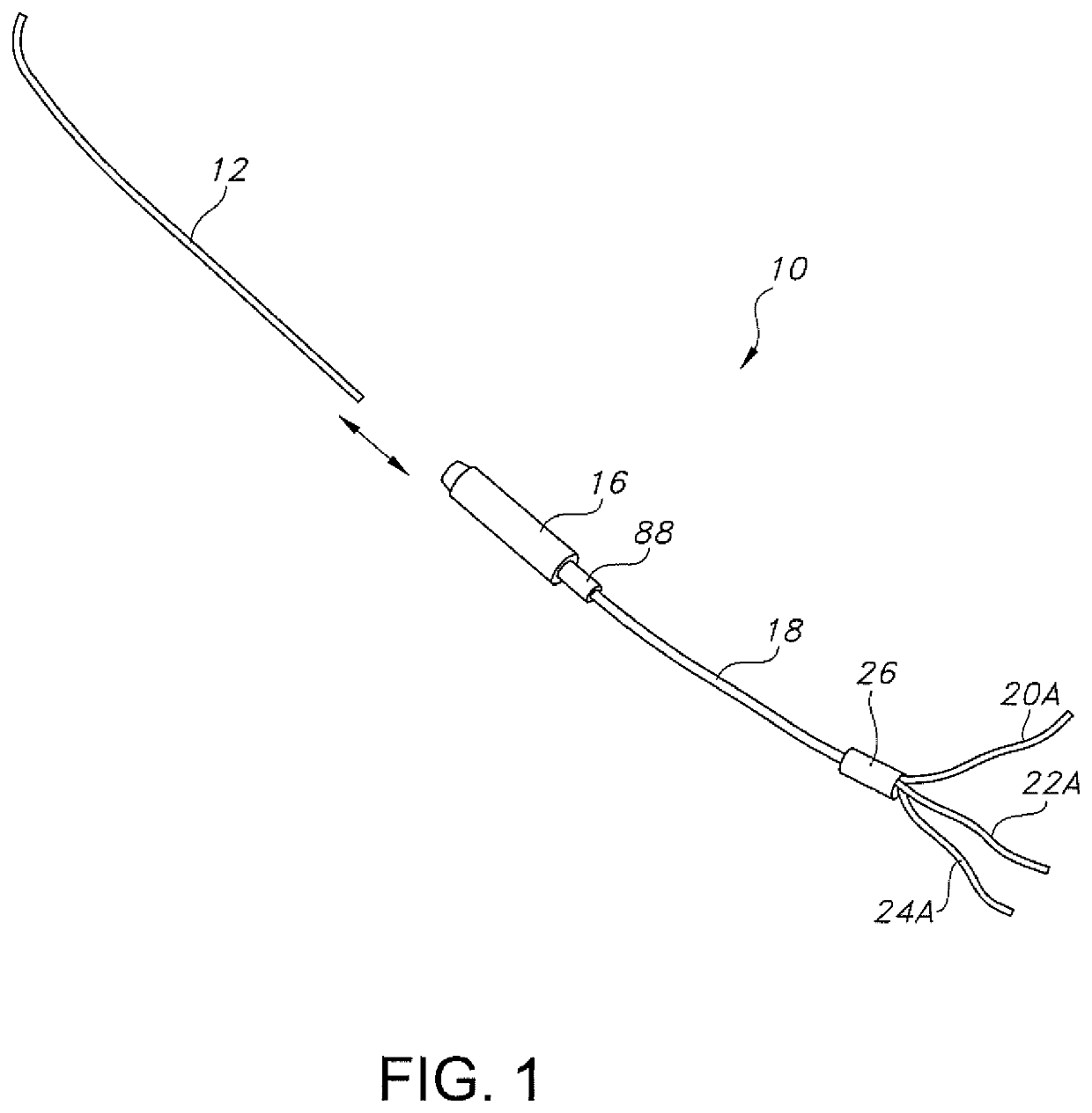
[0042]Turning now to the drawings, FIG. 1 is a schematic of a guidewire system 10 according to the present invention. The guidewire system 10 comprises a guidewire 12 supporting an optical fiber 14 (FIGS. 2, 2A, 2B, 3 to 7, 9, 9A, 9B, 12, 12A, 12B and 13). The guidewire and optical fiber are detachably connectable to an optical connector 16 serving as a handle. An external optical cable 18 is connected to the optical connector 16 opposite the guidewire 12. The guidewire 12 has a length ranging from about 50 cm to about 350 cm.

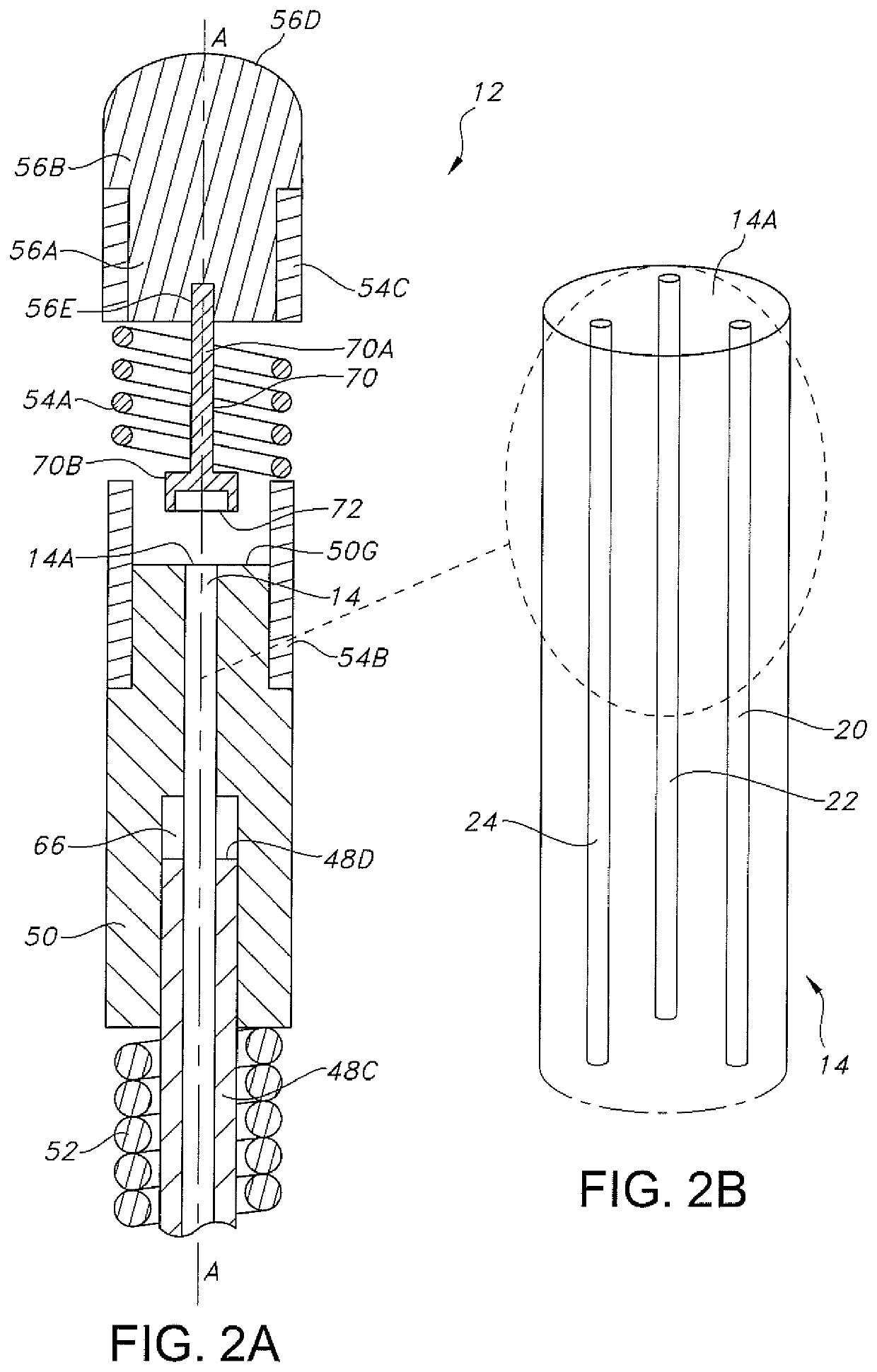
[0043]As will be described in detail hereinafter, in one embodiment the optical fiber 14 supported by the guidewire 12 has three fiber cores 20, 22 and 24 (FIG. 2B). The external optical cable 18 has an external optical fiber 18A (FIGS. 6 and 7) comprising three external fiber cores 20A, 22A and 24A (FIGS. 1 and 8) that are optically connected through the optical connector 16 to the respective fiber cores 20, 22 and 24 of the guidewire optical fiber 14. A proxi...


PUM

PropertyMeasurementUnit
lengthaaaaaaaaaa
outer diameteraaaaaaaaaa

Abstract

A guidewire having a fiber optic force sensor with a mirror having encoded reflectance is described. The guidewire has a distal housing supported by a core wire. A distal hypotube connected to the distal housing supports a spring intermediate hypotube proximal and distal portions. An atraumatic head is connected to the distal hypotube portion. An optical fiber having at least one fiber core extends through lumens in the core wire and housing to a distal end of the housing. A mirror supported by the atraumatic head faces proximally but is spaced distally from the fiber core at a distal face of the optical fiber. The mirror is provided with a pattern of reflectance that varies along a radius from a central area of reflectance. Light of a defined power shines from the fiber core to the mirror with a reflected percentage of the defined light power being reflected back to the fiber core. A percentage of the reflected percentage of the defined light power is captured by and travels along the fiber core to a light wave detector connected to a controller. From the percentage of the reflected percentage of the light of the defined power received by the detector, the controller is programmed to calculate whether an axial or lateral force is imparted to the atraumatic head and, if so, the magnitude and vector of those forces.

Description

CROSS-REFERENCE TO RELATED APPLICATION[0001]This application claims priority to U.S. Provisional Application Ser. No. 62 / 959,234, filed on Jan. 10, 2020.BACKGROUND OF THE INVENTION1. Field of the Invention[0002]The present invention relates to the field of medical devices, and specifically to a guidewire for treating a medical condition in a patient. An exemplary medical condition is the treatment of an occlusion attributed to atherosclerosis.2. Prior Art[0003]Atherosclerosis is the narrowing or occlusion of an artery due to a build-up of plaque and is the most common cause of cardiovascular disease. Occlusions result in impaired blood flow in an artery, which can cause angina, heart attack, heart failure, limb impairment, or limb loss.[0004]To diagnose and treat arteriosclerosis, a guidewire is inserted into the vascular system of a patient through an accessible artery such as the femoral artery. Then, the guidewire is moved through the vasculature to the occluded vessel area. Navi...

Claims


Application Information

Patent Timeline
Patent Type & Authority Patents(United States)
IPC IPC(8): G02B6/02G01L1/24G01D5/26G02B6/44G02B6/24
CPCG02B6/02042G01D5/268G01L1/242G02B6/02004G02B6/4415G02B6/241A61B5/6851A61B2017/00309A61B2017/00849A61B2017/22042A61B34/20A61B34/76A61B2034/2046A61B2034/2055A61B2034/2061G01L5/166G01L5/22
Inventor HAYES, JOHN MICHAELKELLEY, JIM
Owner LAKE REGION MFG
Why Eureka
Try Eureka