
Process for the preparation of a feedstock for a hydroprocessing unit and an integrated hydrotreating and steam pyrolysis process for the direct processing of a crude oil to produce olefinic and aromatic petrochemicals

a hydroprocessing unit and hydrotreating technology, applied in the field of hydroprocessing unit feedstock preparation, can solve the problems of shortening the operational life of the catalyst and the running period of the plant, sulphur can be refractory, and oil is becoming heavier and wors

Active Publication Date: 2021-09-28
SABIC GLOBAL TECH BV
View PDF32 Cites 0 Cited by
  • Summary
  • Abstract
  • Description
  • Claims
  • Application Information

AI Technical Summary

Benefits of technology

The present invention provides a process for preparing a feedstock for a hydroprocessing unit by reducing the aggregation of asphaltenes in crude oil. This results in a catalyst with a long lifespan and a plant that runs for a long time. The process involves separating crude oil into light and heavy components, hydroprocessing the light components to produce a cleaner and more valuable product, and then thermally cracking the heavy components in the presence of steam to produce a mixed product stream. The mixed product stream is then separated and purified to recover olefins and aromatics, as well as a fuel oil blend.

Problems solved by technology

Refineries are facing the challenges of oil becoming heavier and worse.
However, during hydroprocessing carbon deposit and pore blocking on the surface of catalysts are easily to occur because of the congregation and coking of the constituents of asphaltenes, which can greatly shorten the operational life span of the catalyst and the running period of the plant.
Due to the large aromatic structures of the asphaltenes, the sulphur can be refractory in nature and can be difficult to remove.
Precipitated asphaltenes in downstream hydroprocessing units leads to catalyst fouling and lower time-on-stream for the hydroprocessing reactors.
Not only carbon deposit and pore blocking on the surface of catalysts are unwanted phenomena but the presence of high amounts of sulphur in the feedstock as well.

Method used


Image

  • Process for the preparation of a feedstock for a hydroprocessing unit and an integrated hydrotreating and steam pyrolysis process for the direct processing of a crude oil to produce olefinic and aromatic petrochemicals
  • Process for the preparation of a feedstock for a hydroprocessing unit and an integrated hydrotreating and steam pyrolysis process for the direct processing of a crude oil to produce olefinic and aromatic petrochemicals
  • Process for the preparation of a feedstock for a hydroprocessing unit and an integrated hydrotreating and steam pyrolysis process for the direct processing of a crude oil to produce olefinic and aromatic petrochemicals

Examples


embodiment 1

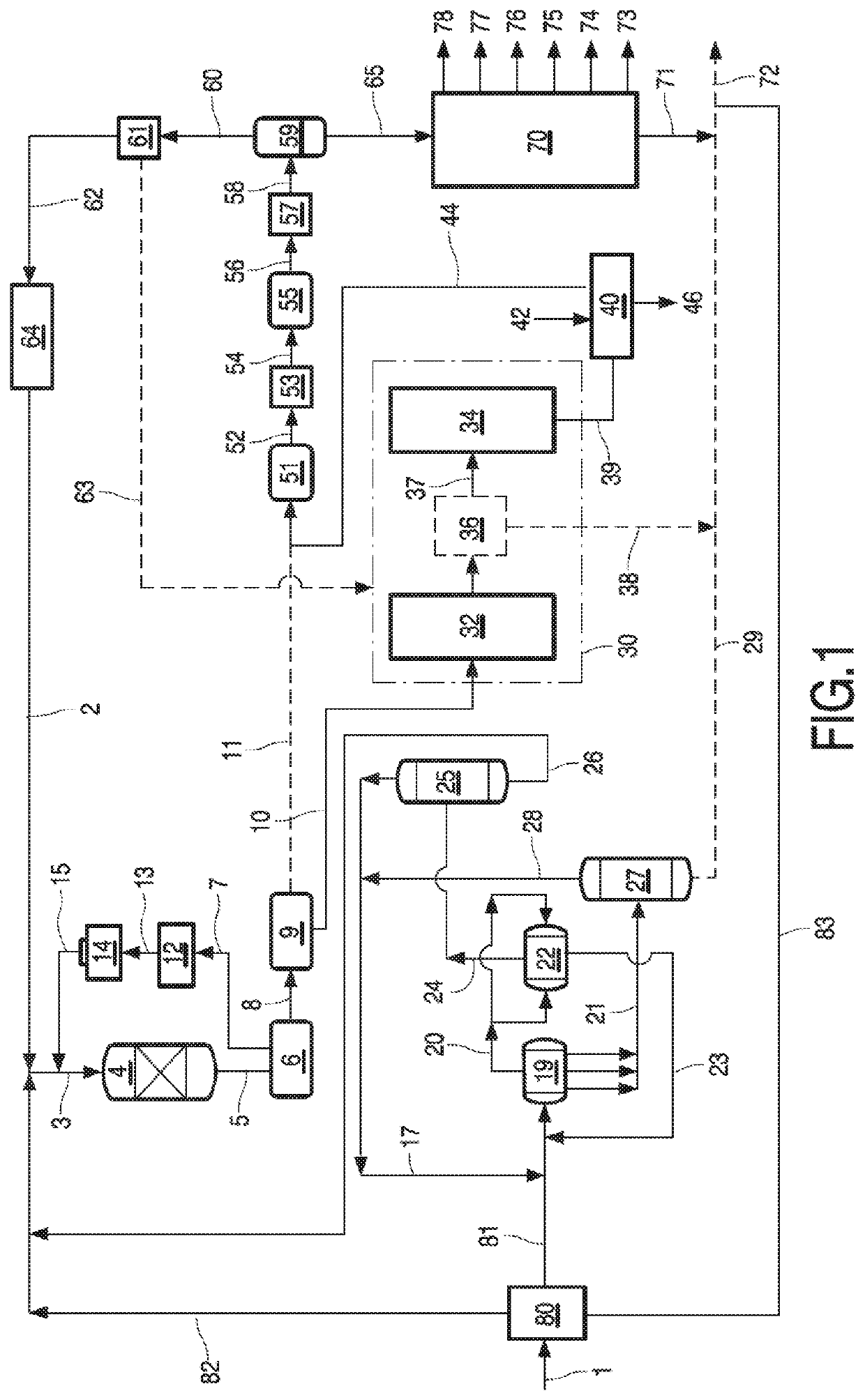
[0042]The present integrated process of embodiment 1 described above preferably further comprises a step of separating the hydroprocessing zone reactor effluents in a high pressure separator to recover a gas portion that is cleaned and recycled to the hydroprocessing zone as an additional source of hydrogen, and a liquid portion, and separating the liquid portion from the high pressure separator in a low pressure separator into a gas portion and a liquid portion, wherein the liquid portion from the low pressure separator is the hydroprocessed effluent subjected to thermal cracking and the gas portion from the low pressure separator is combined with the mixed product stream after the steam pyrolysis zone and before separation in step (d1). According to a preferred embodiment of the present method the thermal cracking step comprises heating hydroprocessed effluent in a convection section of a steam pyrolysis zone, separating the heated hydroprocessed effluent into a vapor fraction and...

embodiment 9

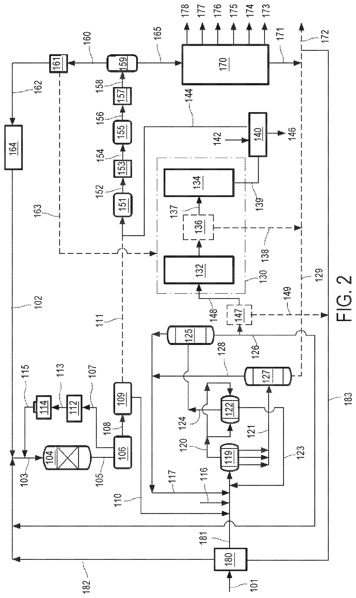
[0069]Another embodiment of the invention is shown with reference to embodiment 9 described above and with reference to FIG. 2. In the process of the present invention, the first solvent deasphalting zone allows to remove certain asphaltenes, metals and carbon residues from the heavy components with a relative high yield of first deasphalted and demetallized oil, but at the expense of a certain level of contamination. The subsequently produced hydroprocessed effluent is then processed in the second solvent deasphalting zone to remove the remaining asphaltenes, metals and carbon residues so that these are not subjected to thermal cracking. In one embodiment, the solvent used in the first solvent deasphalting zone is different than the solvent used in the second solvent deasphalting zone. Preferably, the solvent used in the first solvent deasphalting zone is pentane and the solvent used in the second solvent deasphalting zone is propane or butane. According to this preferred embodimen...

embodiment 17

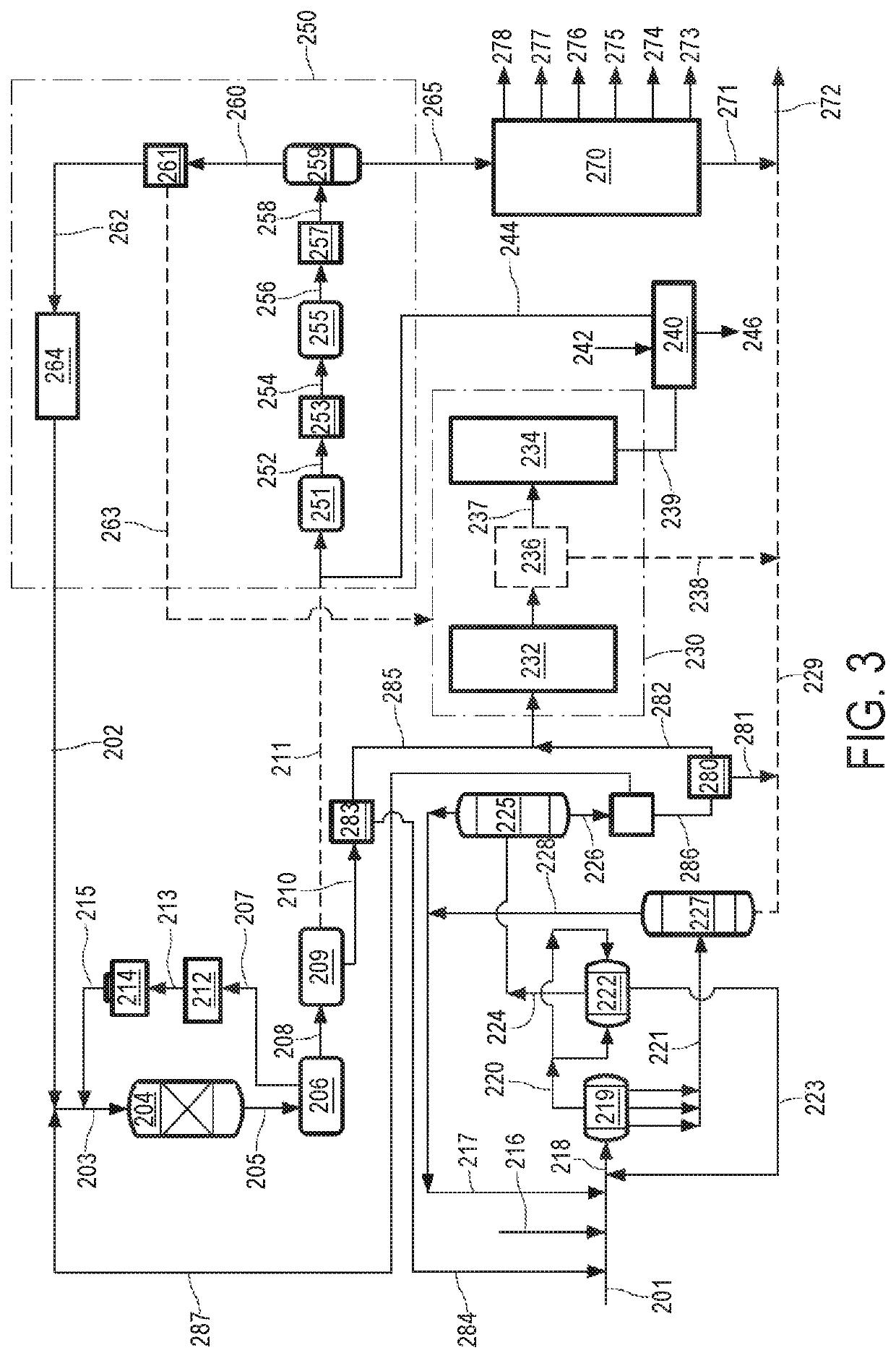
[0099]In the process of the present invention as described in embodiment 17 and shown in FIG. 3, the first solvent deasphalting zone allows to remove certain asphaltenes, metals and carbon residues from the heavy components with a relative high yield of first deasphalted and demetallized oil, but at the expense of a certain level of contamination. The subsequently produced hydroprocessed effluent is then processed in the second solvent deasphalting zone to remove the remaining asphaltenes, metals and carbon residues so that these are not subjected to thermal cracking. In one embodiment, the solvent used in the first solvent deasphalting zone is different than the solvent used in the second solvent deasphalting zone. Preferably, the solvent used in the first solvent deasphalting zone is pentane and the solvent used in the second solvent deasphalting zone is propane or butane. This integrated process further comprises separating the deasphalted and demetallized oil stream in a separat...


PUM

PropertyMeasurementUnit
pressureaaaaaaaaaa
temperatureaaaaaaaaaa
pressureaaaaaaaaaa

Abstract

Integrated hydrotreating and steam pyrolysis processes for the direct processing of a crude oil to produce olefinic and aromatic petrochemicals.

Description

CROSS REFERENCE TO RELATED APPLICATIONS[0001]This application is a national phase application under 35 U.S.C. § 371 of International Application No. PCT / IB2018 / 050683, filed Feb. 2, 2018 which claims the benefit of priority of European Patent Application No. 17154394.5, filed Feb. 2, 2017, European Patent Application No. 17154395.2, filed Feb. 2, 2017, European Patent Application No. 17154391.1, filed Feb. 2, 2017, and European Patent Application No. 17154396.0, filed Feb. 2, 2017, the entire contents of each of which are hereby incorporated by reference in their entireties.FIELD OF THE INVENTION[0002]The present invention relates to a process for the preparation of a feedstock for a hydroprocessing unit, wherein said feedstock is based on crude oil containing asphaltenes.[0003]The present invention also relates to an integrated hydrotreating and steam pyrolysis process for the direct processing of a crude oil to produce olefinic and aromatic petrochemicals.BACKGROUND OF THE INVENTI...

Claims


Application Information

Patent Timeline
Patent Type & Authority Patents(United States)
IPC IPC(8): C10G69/06C10G67/04
CPCC10G69/06C10G2300/206C10G2300/308C10G2400/20C10G2400/22C10G2400/30C10G49/00C10G55/04C10G67/0454C10G9/00C10G19/00
Inventor OPRINS, ARNO JOHANNES MARIAWARDSCHAERLAECKENS, EGIDIUS JACOBA MARIAVAN WILLIGENBURG, JORIS
Owner SABIC GLOBAL TECH BV
Learn More