Antenna module

a technology of antenna modules and fabrication methods, applied in the direction of resonant antennas, substantially flat resonant elements, protective materials radiating elements, etc., can solve the problems of limiting the flexibility of designing the antenna module as a whole, and achieve the reduction of the amount of deformation the suppression of the change rate of the impedance of the signal line 140, and the reduction of the compressive force applied to the signal line 140

Active Publication Date: 2021-10-19
MURATA MFG CO LTD
View PDF21 Cites 1 Cited by
  • Summary
  • Abstract
  • Description
  • Claims
  • Application Information

AI Technical Summary

Benefits of technology

[0005]In the antenna module described in the patent document 1, a power supply line, through which power for driving the radio frequency element is transmitted, needs to transmit larger power compared to other lines. In view of this point, it is conceivable to reduce the resistance value of the power supply line in order to reduce transmission loss of power in the power supply line. To reduce the resistance value of the power supply line, it is conceivable to shorten the length of the power supply line or widen the width of the power supply line. However, when the length of the power supply line is shortened or the width of the power supply line is widened, there is an issue of limiting the flexibility in designing the antenna module as a whole.
[0006]The present disclosure improves the flexibility in designing an antenna module on which an antenna pattern and a radio frequency circuit are mounted.
[0009]The present disclosure enables to improve the flexibility in designing an antenna module on which an antenna pattern and a radio frequency circuit are mounted.

Problems solved by technology

However, when the length of the power supply line is shortened or the width of the power supply line is widened, there is an issue of limiting the flexibility in designing the antenna module as a whole.

Method used


Image

  • Antenna module
  • Antenna module
  • Antenna module

Examples


first embodiment

(Basic Configuration of Communication Device)

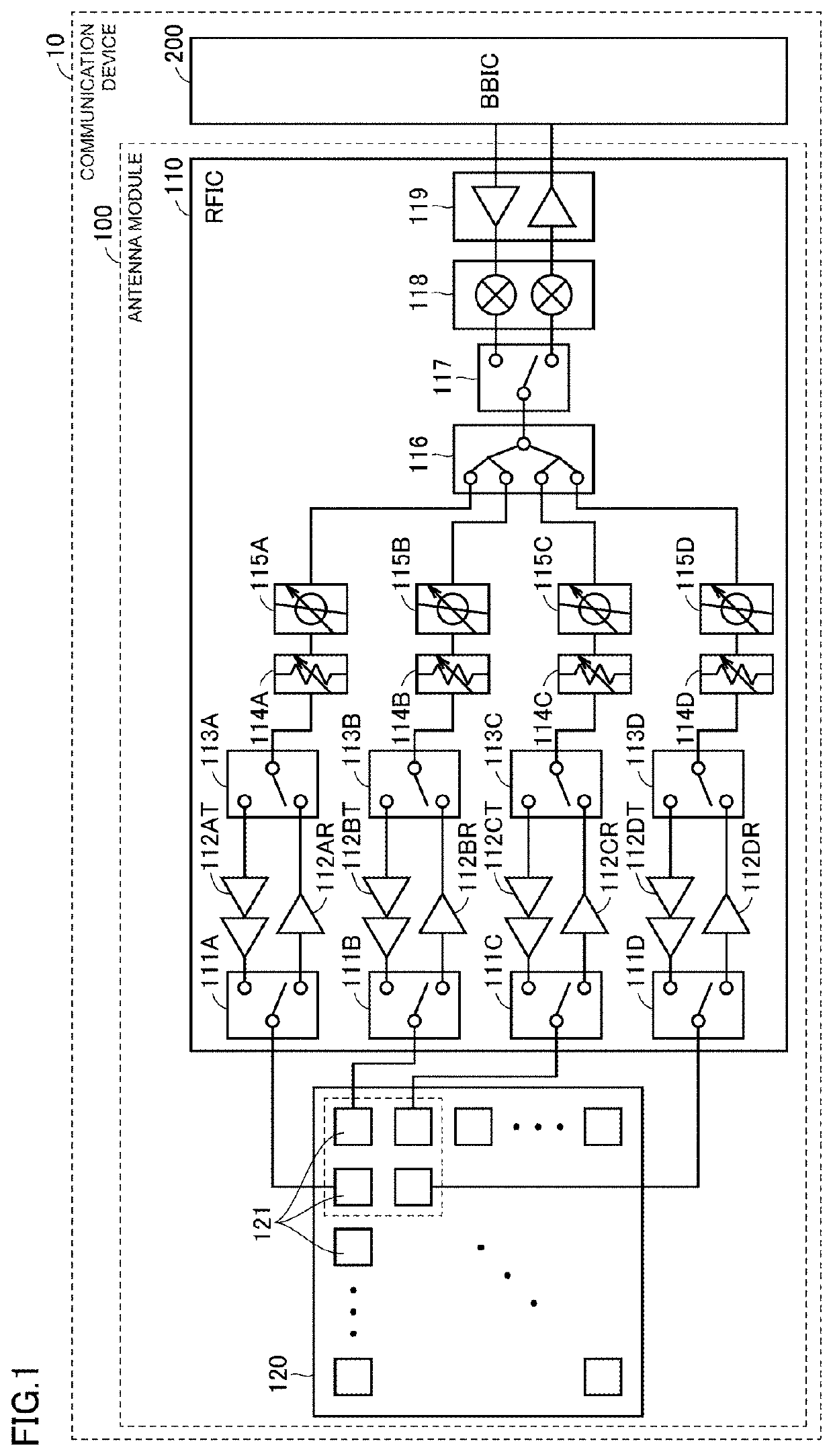
[0026]FIG. 1 is a block diagram of one example of a communication device 10 to which an antenna module 100 according to the present first embodiment is applied. The communication device 10 may be, for example, a mobile phone, a mobile terminal such as a smartphone, a tablet, or the like, or a personal computer with a communication function.

[0027]Referring to FIG. 1, the communication device 10 includes an antenna module 100 and a BBIC 200 that constitutes a base-band signal processing circuit. The antenna module 100 includes a RFIC 110 that is one example of a radio frequency circuit and an antenna array 120. The communication device 10 up-converts a signal sent from the BBIC 200 to the antenna module 100 into a radio frequency signal and radiates from the antenna array 120, and also down-converts a radio frequency signal received by the antenna array 120 and processes a signal at the BBIC 200.

[0028]Note that in FIG. 1, for ease of descri...

second embodiment

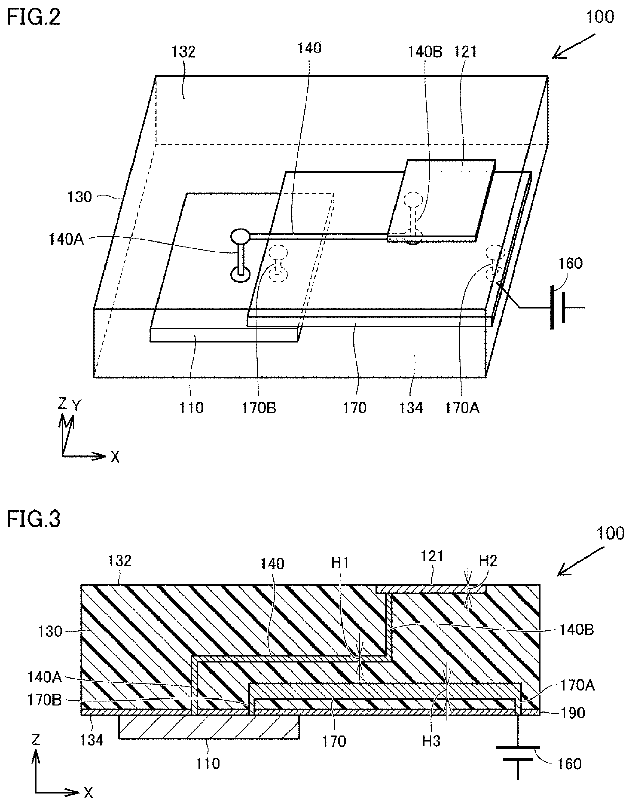
[0077]Next, an antenna module 100B of the second embodiment is described. In the antenna module 100B of the second embodiment, the ground conductor 190 is provided between the power supply line 170 and the antenna pattern 121 in order to suppress the coupling between the power supply line 170 and the antenna pattern 121. Further, in the antenna module 100B of the second embodiment, the ground conductor 190 is provided between the power supply line 170 and the signal line 140 in order to suppress the coupling between the power supply line 170 and the signal line 140.

[0078]FIG. 7 is a cross-sectional view of the antenna module 100B. As illustrated in FIG. 7, the ground conductor 190 is connected to the RFIC 110 by way of a via 190A. Note that the RFIC 110 is provided with a ground line (not particularly illustrated) connected to a ground point provided on an external mounting substrate. That is to say, the ground conductor 190 is connected to the ground point via the RFIC 110. Further...

third embodiment

[0085]In an antenna module 100C of the third embodiment, the power supply circuit 160 is provided on the second surface 134. That is to say, in the antenna module 100C, the RFIC 110 and the power supply circuit 160 are provided on the same surface (second surface 134). FIG. 9 is a cross-sectional view of the antenna module 100C of the third embodiment.

[0086]As illustrated in FIG. 9, in the antenna module 100C, the RFIC 110 and the power supply circuit 160 are provided on the same surface (second surface 134). In the first embodiment and the second embodiment, the power supply circuit 160 is provided outside the antenna module. Compared to the first embodiment and the second embodiment, in the antenna module 100C of the present embodiment, the length L of the power supply line 170 can be shortened. Accordingly, the flexibility in designing the antenna module can be improved while reducing the transmission loss of power in the power supply line 170.

[0087]Note that FIG. 9 illustrates t...


PUM

PropertyMeasurementUnit
thickness H1aaaaaaaaaa
impedanceaaaaaaaaaa

Abstract

An antenna module includes: a dielectric substrate including a multilayer structure, the dielectric substrate having a first surface and a second surface, the second surface being opposite the first surface; an antenna pattern formed on the first surface side of the dielectric substrate; a RFIC provided on the second surface of the dielectric substrate, the RFIC supplying a radio frequency signal to the antenna pattern; and a power supply line that supplies power to the RFIC, wherein the thickness of the power supply line in the stacking direction (Z axis direction) of the dielectric substrate is thicker than the thickness of the antenna pattern in the stacking direction.

Description

[0001]This is a continuation of International Application No. PCT / JP2019 / 030417 filed on Aug. 2, 2019 which claims priority from Japanese Patent Application No. 2018-148428 filed on Aug. 7, 2018. The contents of these applications are incorporated herein by reference in their entireties.BACKGROUNDTechnical Field[0002]The present disclosure relates to antenna modules and fabrication methods for antenna modules, and more specifically to technologies that improve flexibility in designing antenna modules.[0003]Until now, there are proposed antenna modules in each of which an antenna pattern is placed on a first surface of a dielectric substrate and a radio frequency element is mounted on a second surface opposite the first surface. The radio frequency element supplies a radio frequency signal to the antenna pattern (for example, patent document 1).[0004]Patent Document 1: International Publication No. 2016 / 063759 pamphletBRIEF SUMMARY[0005]In the antenna module described in the patent d...

Claims


Application Information

Patent Timeline
Patent Type & Authority Patents(United States)
IPC IPC(8): H01Q1/40H01Q1/38H05K1/02H05K3/46
CPCH01Q1/40H01Q1/38H05K1/0243H05K3/46H05K2201/10098H01Q1/2283H01Q1/243H01Q9/0407H05K1/025H05K1/0265H05K3/4632H05K3/4691H05K2201/10545H01P11/00H01Q23/00
Inventor TAKAYAMA, KEISEISUDO, KAORUTAGO, SHIGERU
Owner MURATA MFG CO LTD
Why Eureka
Try Eureka