

Organic-inorganic hybrid solar cell
a solar cell and organic-inorganic technology, applied in the field of organic-inorganic hybrid solar cells, can solve the problems of low efficiency and stability, and deterioration of stability and properties, and achieve the effects of increasing current density and energy conversion efficiency, enhancing the stability of a device, and improving energy conversion efficiency
- Summary
- Abstract
- Description
- Claims
- Application Information
AI Technical Summary
Benefits of technology
Problems solved by technology
Method used
Image

Examples
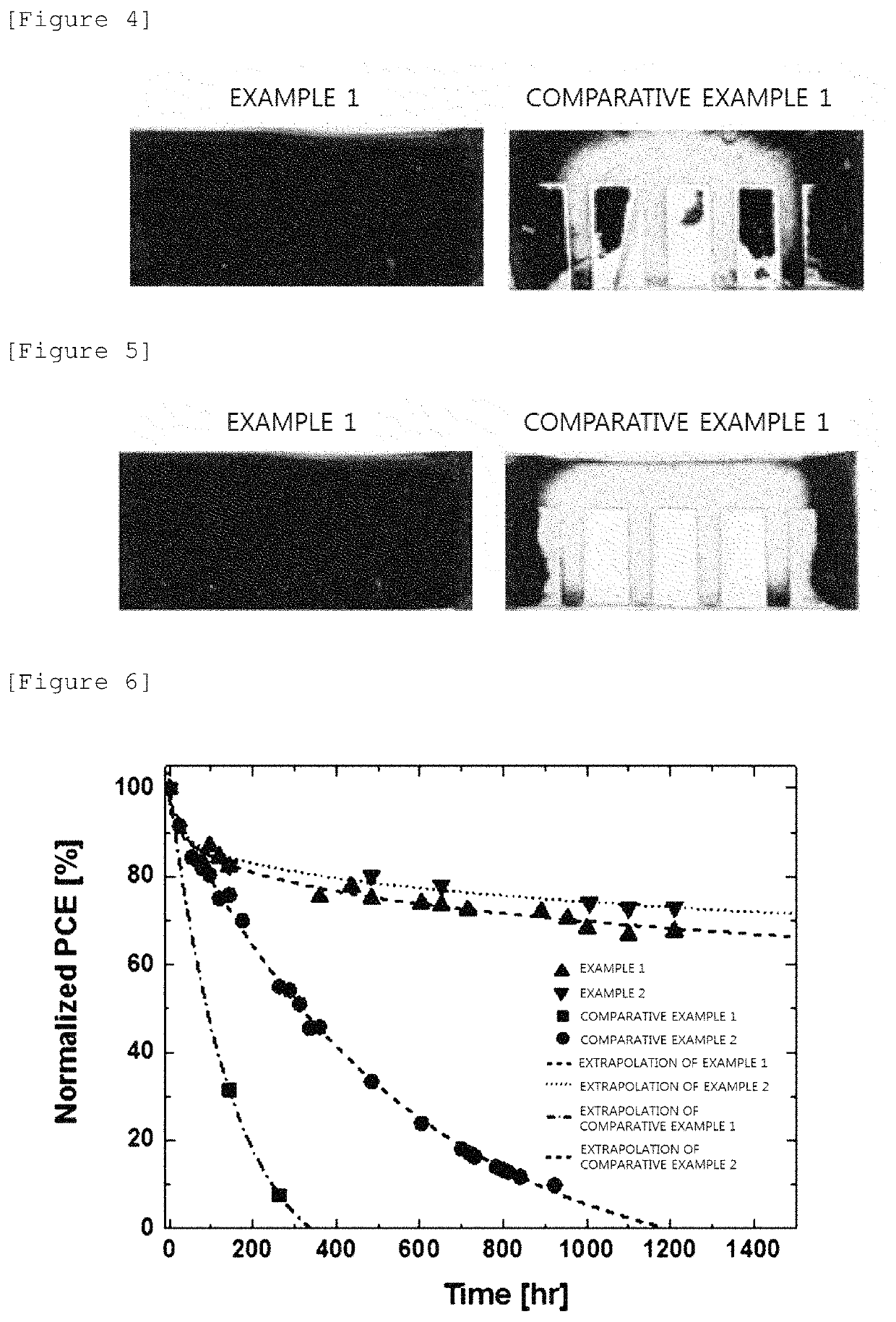
example 1
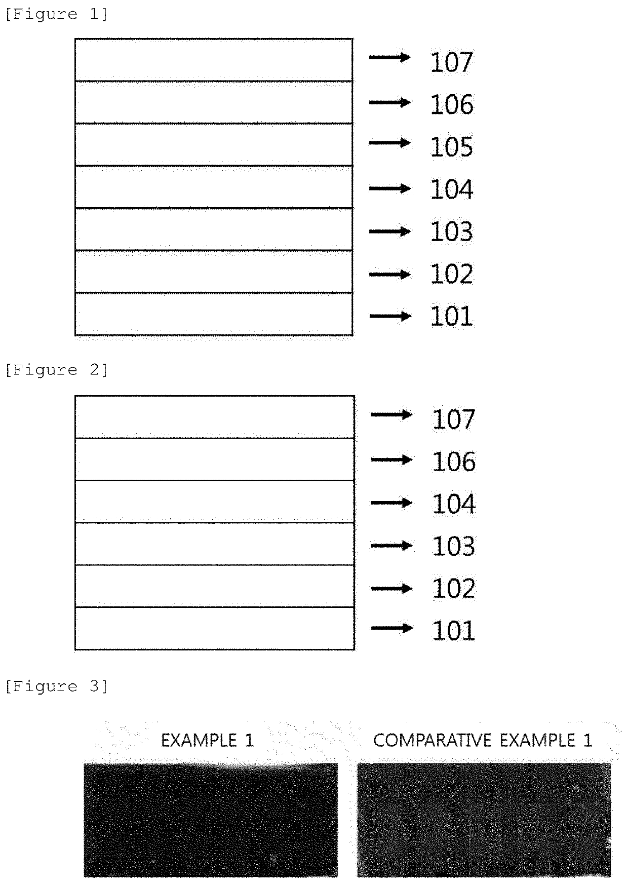
[0099]An organic substrate (40 Ω / sq) coated with indium tin oxide (ITO) was washed in ethanol for 20 minutes by using ultrasonic wave. A first electrode including a conductive transparent base material was manufactured by spin-coating a solution including zinc oxide (ZnO) on the ITO substrate.
[0100]An ITO substrate coated with a ZnO film (hereinafter, referred to as an electron transporting layer) was manufactured by heat-treating the first electrode at 150° C. for about 30 minutes.
[0101]In order to form a first light absorbing layer, a dimethylformamide (DMF) solution in which PbI2 at a concentration of about 40 wt % was dissolved was spin-coated on the electron transporting layer. Thereafter, a first light absorbing layer was formed by spin-coating an isopropyl alcohol (IPA) solution in which CH3NH3I(MAI) at a concentration of 1 wt % was dissolved, and performing a heat treatment at 80° C. for 30 minutes.
[0102]A second light absorbing layer was formed by spin-coating an isopropyl ...
example 2
[0105]An organic substrate (40 Ω / sq) coated with indium tin oxide (ITO) was washed in ethanol for 20 minutes by using ultrasonic wave. A first electrode including a conductive transparent base material was manufactured by spin-coating a solution including zinc oxide (ZnO) on the ITO substrate.
[0106]An ITO substrate coated with a ZnO film (hereinafter, referred to as an electron transporting layer) was manufactured by heat-treating the first electrode at 150° C. for about 30 minutes.
[0107]In order to form a first light absorbing layer, a dimethylformamide (DMF) solution in which PbI2 at a concentration of about 40 wt % was dissolved was spin-coated on the electron transporting layer. Thereafter, a first light absorbing layer was formed by spin-coating an isopropyl alcohol solution in which (HC(NH2)2)0.85 (CH3NH3)0.15I at a concentration of 1 wt % was dissolved, and performing a heat treatment at 100° C. for 30 minutes.
[0108]A second light absorbing layer was formed by spin-coating an...
PUM
| Property | Measurement | Unit |
|---|---|---|
| phase transition temperature | aaaaa | aaaaa |
| phase transition temperature | aaaaa | aaaaa |
| phase transition temperature | aaaaa | aaaaa |
Abstract
Description
Claims
Application Information