Mixture formation device for a gas engine and gas engine

a technology of mixing formation device and gas engine, which is applied in the direction of machines/engines, combustion air/fuel air treatment, combustion-air/fuel-air treatment, etc., can solve the problems of not being suitable, requiring considerable additional control and regulation resources, and not being able to inject gas into the combustion chamber of the internal combustion engine by means of a conventional fuel pump. achieve the effect of simple and cost-effectiv

Active Publication Date: 2021-11-23
VOLKSWAGEN AG
View PDF35 Cites 3 Cited by
  • Summary
  • Abstract
  • Description
  • Claims
  • Application Information

AI Technical Summary

Benefits of technology

[0008]The invention is thus based on the objective of allowing a simple and cost-effective mixture formation of a gaseous fuel for an internal combustion engine, whereby the strict limit values set by the emissions legislation are met and a dynamic engine operation is possible without entailing function losses or emission disadvantages.
[0009]According to the invention, this objective is achieved by a mixture formation device for installation in an intake channel of an internal combustion engine operated with a combustible gas, comprising a closing member with which the opening cross section of the intake channel of the internal combustion engine can be reduced, also comprising at least one metering valve for metering the combustible gas into the intake channel of the internal combustion engine, as well as at least one connector for an exhaust gas recirculation line of the internal combustion engine, whereby the deflecting geometry of the closing member diverts a fresh air stream into a first ring channel, especially into a diffuser, and whereby a first feed point for the combustible gas and a second feed point for the gas that has been recirculated via the exhaust gas recirculation line are arranged downstream from the place with the deflecting geometry. This makes it possible to create a component which, in a compact installation space and in a cost-effective manner, has the functions of a quantity regulator for the fresh air stream and of a gas mixer and also fulfills the functions of flow guidance and flow optimization. Moreover, relatively good mixture processing at a low flow resistance can be achieved.
[0010]Owing to a Venturi effect during the flow through the mixture formation device, a smaller mass of fuel gas has to be introduced into the mixture formation device since the pressure in the area of the intake pressure in the flow section situated upstream from the mixture formation device is reduced, as a result of which the dynamics in the area of the fuel gas feed are improved. Moreover, the higher dynamics and the reduced pressure allow greater gas recirculation rates, without the recirculated exhaust gas accumulating in the exhaust gas recirculation line. In this context, less discharge work is needed so that the fuel gas consumption can be reduced by such a mixture formation device.

Problems solved by technology

Particularly in the case of compressed natural gas (CNG), it is a challenge to feed the gas into the combustion chambers of the internal combustion engine.
Since gases are far more compressible than (virtually incompressible) liquids, such a gas cannot be injected into the combustion chamber of the internal combustion engine by means of a conventional fuel pump.
A drawback of such mixers having a fixed geometry, however, is that, although they deliver good results at a stationary operating point such as, for instance, in the case of an internal combustion engine of a cogeneration power station, they are rather unsuitable or call for considerable additional control and regulation resources when it comes to a dynamic operation of the type needed in a motor vehicle.

Method used


Image

  • Mixture formation device for a gas engine and gas engine
  • Mixture formation device for a gas engine and gas engine
  • Mixture formation device for a gas engine and gas engine

Examples


Embodiment Construction

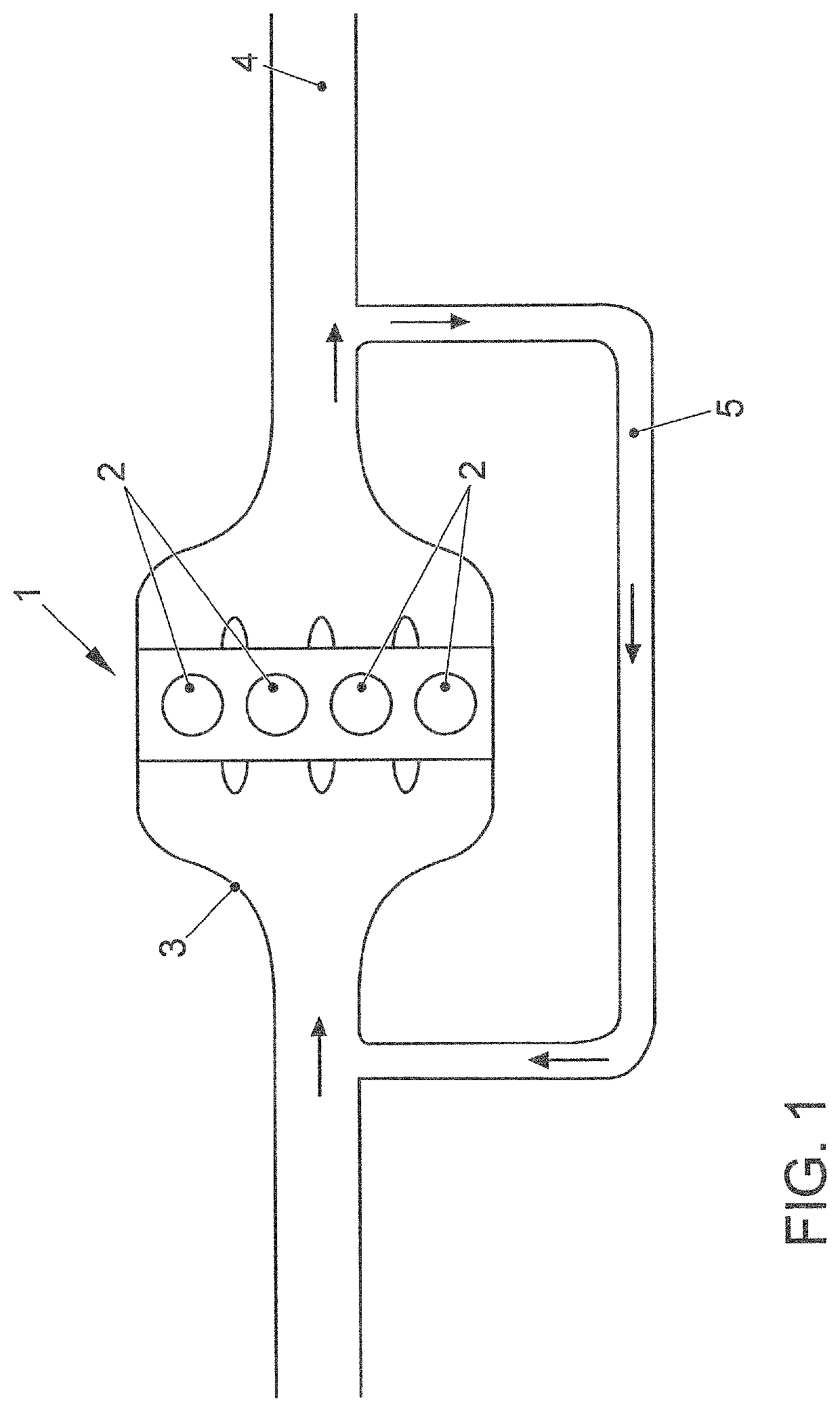
[0041]FIG. 1 shows a greatly simplified structure of an internal combustion engine 1 with four combustion chambers 2, an intake channel 3 as well as an exhaust gas channel 4. Here, an exhaust gas recirculation line 5 is provided which connects the exhaust gas channel 4 to the intake channel 3 and thus allows burned fuel contents to be recirculated to the intake channel 3 of the internal combustion engine 1. The internal combustion engine 1 in the embodiment described below is configured as a gas engine 1 and is operated with a gaseous fuel, preferably by natural gas (compressed natural gas—CNG). As an alternative, operation with a liquefied gas (liquefied natural gas—LNG) is likewise possible. Gas engines 1 differ from classic internal combustion engines—where a liquid fuel is metered into the intake channel 3 or into the combustion chambers 2—in that the fuel is gaseous and thus highly compressible at ambient temperature and ambient pressure. As a result, the gaseous fuel cannot, o...


PUM


Abstract

A mixture formation device for an internal combustion engine operated with a burnable gas, preferably compressed natural gas CNG, comprises a combination of a quantity regulator, a gas mixer, a flow-guiding element for pressure recovery, and a connection possibility for exhaust gas recirculation of the internal combustion engine. The mixture formation device according to the invention can empty a gas tank to a comparatively low pressure of approx. 2 bar, an excellent mixture formation being achieved over the entire range of speed and load range of the internal combustion engine. According to the invention, such a mixture formation device can reduce production costs as well as space requirements compared to known solutions. An internal combustion engine operated with a burnable gas, particularly compressed natural gas (CNG), may also comprise such a mixture formation device in the intake tract thereof.

Description

CROSS-REFERENCE TO RELATED APPLICATIONS[0001]This application is a National Phase Application of PCT International Application No. PCT / EP2017 / 080634, International Filing Date Nov. 28, 2017, claiming priority of German Patent Application No. 10 2016 123 826.0, filed Dec. 8, 2016, which is hereby incorporated by reference.FIELD OF THE INVENTION[0002]The invention relates to a mixture formation device for an internal combustion engine operated with a combustible gas as well as to an internal combustion engine in whose intake tract such a mixture formation device is arranged.BACKGROUND OF THE INVENTION[0003]The state of the art discloses internal combustion engines which are operated with a combustible gas, for example, liquefied natural gas (LPG) or compressed natural gas (CNG). Particularly in the case of compressed natural gas (CNG), it is a challenge to feed the gas into the combustion chambers of the internal combustion engine. Since gases are far more compressible than (virtually...

Claims


Application Information

Patent Timeline
Patent Type & Authority Patents(United States)
IPC IPC(8): F02D19/02F02M21/02F02M26/19F02M21/04F02M35/10
CPCF02D19/023F02M21/0278B01F2215/0086F02M21/0281F02M21/047F02M26/19F02M35/10222F02M21/042F02M26/51Y02T10/30B01F2101/503
Inventor KLÜTING, CHRISTIAN-B.BEGER, FRANKKIEL, MARTIN
Owner VOLKSWAGEN AG
Why Eureka
Try Eureka