Device, use of the device and a method for high-contrast imaging

a high-contrast imaging and optical probe technology, applied in the field of optics, can solve the problems of difficult to assess the density distribution of the material above the nozzle, difficult to measure the density distribution or parametrize the properties of the gas jet with high, and allow proper imaging. , to achieve the effect of increasing the effect of the object on polarization and anisotropy

Active Publication Date: 2022-04-05
FYZIKALNI USTAV AV CR V V I
View PDF5 Cites 0 Cited by
  • Summary
  • Abstract
  • Description
  • Claims
  • Application Information

AI Technical Summary

Benefits of technology

[0013]The present invention thus provides a device, resp. method as described below, for analysis of structural characteristics of objects under investigation with improved sensitivity while keeping the spatial resolution of the characterization unaffected.
[0024]According to another embodiment, the device further comprises a half-wave plate positioned between the beam splitter and the object. This embodiment allows probing optical anisotropy of the object (the phase-shift of the probe induced by the object in dependence on the direction of linear polarization of the probe).
[0027]The present embodiment is particularly useful for further increasing the signal to noise ratio of the characterization of an object that does not change the polarization state of the probe.
[0029]The embodiment as described above provides the possibility to further increase the sensitivity (or signal-to-noise ratio) by multiple interactions of the probe beam with the object while preserving the spatial information by self-imaging of the object. This embodiment is particularly useful for probing an object which does not change a polarization of the probing beam.
[0069]1) spatially resolved absorption or reflectivity of the object—increasing the absorption (reflectivity) contrast due to multiple interactions,
[0071]3) spatially resolved optical anisotropy—increasing the effect of the object on polarization of the probe by multiple interactions.

Problems solved by technology

Gas targets can be of different density and it is especially difficult to assess its density distribution above the nozzle.
Therefore, it is challenging to measure density distribution or even parametrize the properties of the gas jet with high precision for low density gas jets with small dimensions.
However, it does not allow proper imaging, so the information about spatial distribution is lost.
There is, however, only one pass of the probe through the object possible, which results in rather low sensitivity of the measurement.
In particular, if the signal-to-noise ration of the return signal is 1:10, attenuation by the gas would cause a reduction in return signal that is equal to the noise level and therefore making it undetectable.
The present solution, however, has drawbacks, such as involving at least two detectors (an infrared video camera and visible light video camera) and corresponding electronics in order to visualise the resulting picture of the gas.

Method used


Image

  • Device, use of the device and a method for high-contrast imaging
  • Device, use of the device and a method for high-contrast imaging
  • Device, use of the device and a method for high-contrast imaging

Examples


Embodiment Construction

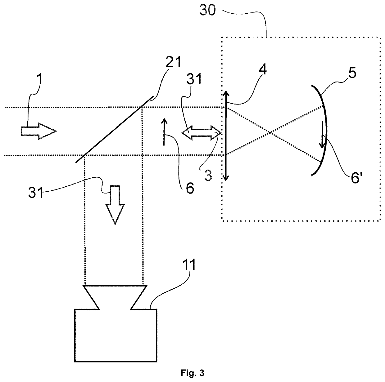
[0084]FIG. 3 shows a first embodiment of the present invention. In the first embodiment, an incident beam 1 of optical radiation is directed to a beam splitter 21. The beam splitter 21 which splits the incident beam 1 into a probe beam 3 and reference beam 7. Probe beam 3 is further directed to an object under investigation (e.g. a gas target) 6. Gas, for example, may escape from a gas jet. The probe beam 3 is further directed to a self-imaging system 30 for receiving the probe beam 3 from the object 6. Such a self-imaging system 30 is capable of imaging the object 6 on itself. In a preferred embodiment, the system 30 preserves the reflected beam 31 divergence. In a preferred embodiment, the system 30 comprises a lens 4 which focuses the probe beam 3 in front of a concave mirror 5 and creates an image 6′ of the object 6 on that mirror 5. The mirror 5 reflects the probe beam 3 back to the lens 4, providing a reflected probe beam 31. In a preferred embodiment the concave mirror 5 crea...


PUM

PropertyMeasurementUnit
backing pressuresaaaaaaaaaa
transparentaaaaaaaaaa

Abstract

The present invention relates to a device, use of the device and a method for high contrast imaging, particularly suitable for imaging of moving object of interest such as gas expanding from a gas jet or physical or chemical or biological processes in material.The device for high-contrast imaging comprises a beam splitter for splitting a beam into a probe beam and a reference-beam, wherein the probe beam is directed to an object; a self-imaging system for receiving the probe beam from the object and imaging the object on itself while in a preferred embodiment, the system preserves a reflected probe beam divergence. The beam interacts with the object at least twice; and the reflected probe beam is further directed to the splitter after the last interaction; and detection means receiving the probe beam from the splitter.

Description

[0001]This application is the continuation of International Application No. PCT / CZ2020 / 050009, filed 4 Mar. 2020, which claims the benefit of Luxembourg patent application LU 101150, filed 14 March August 2019, the entire contents of which are hereby incorporated by reference.TECHNICAL FIELD[0002]The present invention relates to optics, in particular to a device and a method for optical probing, preferably but not exclusively for gas jet characterization, the method and device use optical means. More particular, the present invention concerns a device and a method for high-contrast imaging.BACKGROUND ART[0003]Gas targets are frequently used for interactions between high power lasers and gaseous medium, in particular for laser wakefield accelerators. Gas targets can be of different density and it is especially difficult to assess its density distribution above the nozzle. The gas density may vary, but it is usually between 1016 atoms / cm3 to 1019 atoms / cm3 and the target lengths vary ...

Claims


Application Information

Patent Timeline
Patent Type & Authority Patents(United States)
IPC IPC(8): G01N21/45G01N21/39G01N21/78
CPCG01N21/45G01N21/39G01N21/783G01N2021/1765G01N21/21G01N21/27
Inventor NEJDL, JAROSLAVALBRECHT, MARTINVAN{HACEK OVER (C)}URA, JAKUB
Owner FYZIKALNI USTAV AV CR V V I
Why Eureka
Try Eureka