Wafer holder and wafer transfer apparatus, system and method

a technology of wafer holder and transfer apparatus, applied in the field of semiconductor technology, can solve the problems of undermining the vacuum retention ability of the holder, and achieve the effects of enhancing deformation, enhancing deformation, and extending service li

Active Publication Date: 2022-04-19
SHANGHAI MICRO ELECTRONICS EQUIP (GRP) CO LTD
View PDF27 Cites 0 Cited by
  • Summary
  • Abstract
  • Description
  • Claims
  • Application Information

AI Technical Summary

Benefits of technology

[0053]In the wafer holder and wafer transfer apparatus, system and method of the present disclosure, the groove provided at the outer side of the joint between the first skirt and the first opening is able to relieve stresses produced at a base portion of the sucker during deformation of the first skirt. In this way, compared to a wafer holder without such a groove, the wafer holder allows the first skirt to experience a greater amount of deformation with the same thickness or the same amount of deformation with an increased thickness. As a result, in the case that the first skirt experiences a greater amount of deformation with the same thickness, the wafer holder can accommodate a wafer with a greater warpage to avoid air leakage in vacuuming the space formed by a suction surface of the wafer. Moreover, in the case that the first skirt has an increased thickness with the same deformability, the first skirt will be tougher in structure and less prone to damage during use. As a result, the first skirt will experience less wear and tear, so its service life and even that of the wafer holder will be extended. This can dispense with the need for frequent replacement of the wafer holder and resulting in enhanced production efficiency.
[0054]Additionally, the increased deformability allows a wafer to be effectively brought into contact with the wafer supports and the first skirt provides supporting forces not exceeding the wafer's weight. In other words, the wafer can tightly adhere to the wafer supports and thus be transferred with high accuracy during with the frictional force between the wafer supports and the wafer is greater than zero. The wafer supports are designed to support a warped wafer and provide it with friction during its movement, which can prevent the wafer from displacement relative to the wafer transfer apparatus body so that the wafer will be always secured to the wafer holders without the risk of slipping off the apparatus.
[0055]Furthermore, according to the present disclosure, the second and third skirts in each first fixing member are compressed against a smooth surface, so the holder body can be retained on the apparatus body by a pressure difference between the interior and the exterior of the first fixing member. That is, the first fixing member functions in the same way as a vacuum sucker to fixedly fasten the wafer holder onto the wafer transfer apparatus. This allows easy, efficient attachment and replacement of the wafer holder simply by a pressing action. By contrast, conventional rubber wafer holders are attached to wafer transfer apparatuses by adhesives. When such a wafer holder is detached for replacement, adhesive residues tend to remain on the surface of the apparatus body and the holder body, which require a cumbersome long-lasting removal process involving washing, wiping and even use of a scraper and probably leaving scratches on the surface of the apparatus body. Moreover, this conventional approach requires an additional room between the holder and the transfer apparatus for accommodating the adhesive, which may deteriorate the accuracy in wafer transfer. Therefore, the apparatus according to this embodiment allows more efficient replacement of wafer holders with a shortened process cycle and improved wafer transfer accuracy.
[0056]According to this embodiment, with the suction surface, which is lower than the body surface, and against which the second skirt, third skirt and the bottom surface of the sucker are tightly pressed, the apparatus body can have a reduced overall vertical dimension. In addition, in order to facilitate secure mounting for the wafer holder, the suction surface may be a smooth, dense surface with a size greater than those of the compressed second and third skirts.
[0058]After the wafer holder is mounted to the transfer apparatus, a vertical distance between top surfaces of the first skirt and wafer support determines an amount of wafer warpage that the wafer holder can accommodate. Therefore, the greater the deformation of the first skirt is, the more sufficiently the wafer holder can accommodate the wafer warpage. While an increase in the skirt thickness can result in an extended service life of the skirt, but it is unfavorable to the deformability thereof. According to the present disclosure, the annular groove can either enhance the deformability with an increased skirt thickness or maintain the deformability with an even increased skirt thickness. Furthermore, since the wafer holders on the apparatus can be distributed in a circular pattern encompassed by the outline of a wafer, the transfer apparatus having the wafer holders can accommodate a great wafer warpage than the wafer warpage a single wafer holder can accommodate.
[0059]The wafer holder of the present disclosure can be also used in wafer pre-alignment apparatuses whose functions involve the fixation or transfer of wafers. Similarly, in this case, the wafer holder will well accommodate wafer warpage, enhance transfer accuracy and allows for more reliable retention.

Problems solved by technology

With the development of semiconductor technology, thinning processes and bonding processes cause a certain degree of warpage in a wafer, and when loaded on a fork-shaped wafer holder, some portions of the wafer will not come into contact with a suction surface of the holder and leave air gaps therebetween, which may undermine the vacuum retention ability of the holder.

Method used


Image

  • Wafer holder and wafer transfer apparatus, system and method
  • Wafer holder and wafer transfer apparatus, system and method
  • Wafer holder and wafer transfer apparatus, system and method

Examples


embodiment 1

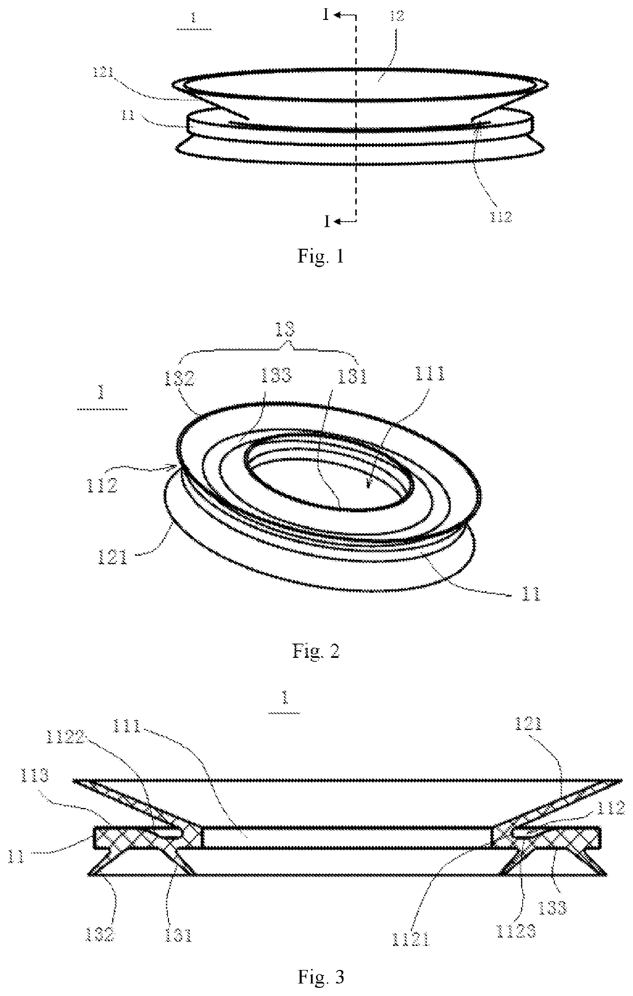
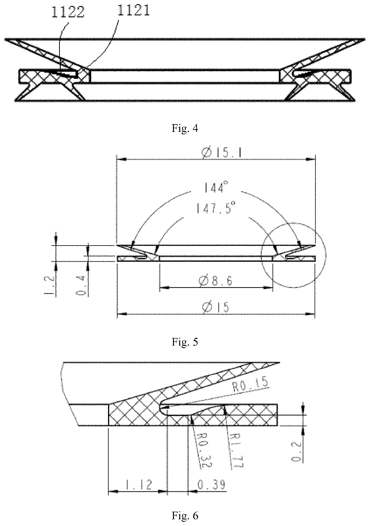
[0071]FIGS. 1 to 2 are structural schematics of a wafer holder according to a first embodiment of the present disclosure. As shown, the wafer holder 1 includes a holder body 11 and a sucker 12. The holder body 11 defines a first opening 111, while the sucker 12 includes a first skirt 121 that is located on one side of the holder body 11 and connected at the bottom to the first opening 111. FIGS. 3-4 show schematic cross-sectional views of the wafer holder. As shown, a groove 112 is formed at the joint between the first skirt 121 and the first opening 111, and is located at an outer side of the first skirt 121.

[0072]Specifically, as shown in FIGS. 3 to 4, the first opening 111 may be circular, while the holder body 11 may appear, in general, as a hollow cylinder, with an internal surface delimiting the first opening 111. The first skirt 121 may have a general shape of a truncated cone and may be formed of an elastic wall connected at the bottom to the internal surface of the holder b...

embodiment 2

[0076]In this embodiment, a wafer transfer apparatus is provided. The wafer transfer apparatus includes an apparatus body 2 and a plurality of the wafer holders 1 of Embodiment 1. The wafer holders 1 are all mounted onto the apparatus body 2 and each include a holder body 11 and a sucker 12. The holder body 11 defines a first opening 111, while the sucker 12 includes a first skirt 121 that is located on one side of the holder body 11 and connected to the first opening 111. A groove 112 is formed at the joint between the first skirt 121 and the first opening 111, and is located at an outer side of the first skirt 121.

[0077]The wafer transfer apparatus may further include a plurality of wafer supports 3 and a seal 4. The seal 4 may be a sheet-like component. The apparatus body 2 may define a plurality of first holes 21 being circular and have a bottom surface in which a trench 22 is formed in communication with the first holes 21 and a top surface. The wafer supports 3 may be cylindri...

embodiment 3

[0090]According to the present embodiment, a wafer transfer system is provided. The wafer transfer system includes the wafer transfer apparatus of Embodiment 2, a robotic arm and a wafer cassette. The wafer transfer apparatus is secured to the robotic arm which is configured to move the wafer transfer apparatus into the wafer cassette to pick up or place a wafer from or into the wafer cassette, so that the wafer can be transported by the wafer transfer apparatus moving with the robotic arm.

[0091]Specifically, the wafer cassette may include a plurality of wafer slots for storing wafers. The sum of a thickness of the wafer transfer apparatus (i.e., a thickness of the apparatus body plus a thickness of the wafer holders), a thickness of any stored wafer, a height difference between a lower position for entry of the wafer transfer apparatus into the wafer cassette and a higher position for exit of the wafer transfer apparatus from the wafer cassette may be less than a slot-to-slot space...


PUM

PropertyMeasurementUnit
heightaaaaaaaaaa
heightaaaaaaaaaa
outer diameteraaaaaaaaaa

Abstract

A wafer holder and a wafer transfer apparatus, system and method are disclosed. The wafer holder is mounted onto the wafer transfer apparatus and includes a holder body and a sucker. The holder body defines a first opening, while the sucker includes a first skirt. The first skirt is located on one side of the holder body and connected to the first opening. A groove is formed at a joint between the first skirt and the first opening. The groove is located at an outer side of the first skirt, and is able to relief stresses produced at a base portion of the sucker during deformation of the first skirt.

Description

TECHNICAL FIELD[0001]The present disclosure relates to semiconductor technology and, in particular to a wafer holder and a wafer transfer apparatus, system and method.BACKGROUND[0002]In the field of semiconductor, robotic arms are used to retain wafers on their fork-shaped holders by vacuum forces and then move to transport the retained wafers. With the development of semiconductor technology, thinning processes and bonding processes cause a certain degree of warpage in a wafer, and when loaded on a fork-shaped wafer holder, some portions of the wafer will not come into contact with a suction surface of the holder and leave air gaps therebetween, which may undermine the vacuum retention ability of the holder.[0003]Therefore, it is desired to design a wafer holder and a wafer transfer apparatus, system and method for effectively holding warped wafers.SUMMARY OF THE DISCLOSURE[0004]An objective of the present disclosure is to provide such a wafer holder and a wafer transfer apparatus,...

Claims


Application Information

Patent Timeline
Patent Type & Authority Patents(United States)
IPC IPC(8): H01L21/68H01L21/683B65G47/91H01L21/67H01L21/677
CPCH01L21/6838B65G47/91H01L21/67017H01L21/67742H01L21/67754H01L21/67766H01L21/68H01L21/68707H01L21/687
Inventor WANG, GANGZHANG, RONGJUNJIANG, XIAOYUSHI, YICHAOLIU, KAICHEN, JUNPENG
Owner SHANGHAI MICRO ELECTRONICS EQUIP (GRP) CO LTD
Why Eureka
Try Eureka