Supercharge Your Innovation With Domain-Expert AI Agents!

RF connector comprising a flat central contact with a fork shaped end and a solid insulating structure configured to guide a complimentary contact pin, applicable for use in a board to board connector

a technology of rf connector and complimentary contact pin, which is applied in the direction of coupling contact members, coupling device connections, securing/insulating coupling contact members, etc., can solve the problems of high production cost, large limitation of axial and radial misalignment allowed for board-to-board connections, and all known board-to-board connections present significant drawbacks

Active Publication Date: 2022-08-16
RADIALL SA
View PDF13 Cites 0 Cited by
  • Summary
  • Abstract
  • Description
  • Claims
  • Application Information

AI Technical Summary

Benefits of technology

The invention is a new type of RF coaxial connector that is cheaper to make than previous versions. It uses a central contact that can be produced using low-cost techniques like cutting metal sheets. In an advanced version, the connector has a solid insulating structure with slots where the branches of the central contact can move around and deform without being crushed. This design helps to prevent damage to the connector during installation.

Problems solved by technology

The major drawback is the great limitation on the axial and radial misalignments allowed for these connections.
However, all the known board-to-board connections do present a significant number of drawbacks due to the conception of the RF coaxial components.
Firstly, a slotted sleeve has not only high production cost, but also has high processing requirements. More particularly, the central female contact has an inner hole at the end, and in most cases, the inner hole is a blind hole. After the turning process, the fluid, that is used for cutting, needs to be cleaned, which is difficult to be properly cleaned, and the inner hole is black after the heat treatment when incorrect cleaning and presence of residues. When applying an electroplating process, the inner hole is not easily plated with a plating layer to cover the residues. Besides, at the time of electroplating, the central female contact has a large difference in current density between the interior of hole and the exterior of the hole. Generally, the current density outside the hole is high, the plating layer is thick, the current density in the hole is low, and the plating layer is thin. At the same time, the plating solution in the hole is difficult to be recycled, and the plating material is not easily replenished after being consumed, and the plating layer in the hole is further thinned than the outside the hole.
In order to ensure sufficient thickness of the plating layer in the hole, the entire product must be plated with a thick plating layer, which consumes a large amount of electroplated precious metal, consumes a large amount of energy, has a long working time, and has a high cost.
However, the product can only be plated by vibrating or the like in the barrel.
That is the reason why the thickness of the plating layer of the entire product must be increased again, resulting in waste of plating materials, working time and electricity.
Secondly, a slotted sleeve can be difficult to be mounted and fixed notably in rotation, so that the assembled RF coaxial connector can be damaged.

Method used


Image

  • RF connector comprising a flat central contact with a fork shaped end and a solid insulating structure configured to guide a complimentary contact pin, applicable for use in a board to board connector
  • RF connector comprising a flat central contact with a fork shaped end and a solid insulating structure configured to guide a complimentary contact pin, applicable for use in a board to board connector
  • RF connector comprising a flat central contact with a fork shaped end and a solid insulating structure configured to guide a complimentary contact pin, applicable for use in a board to board connector

Examples


Embodiment Construction

[0056]Other advantages and features of the invention will become more apparent on reading the detailed description of exemplary implementations of the invention, given as illustrative and non-limiting examples with reference to the following figures in which:

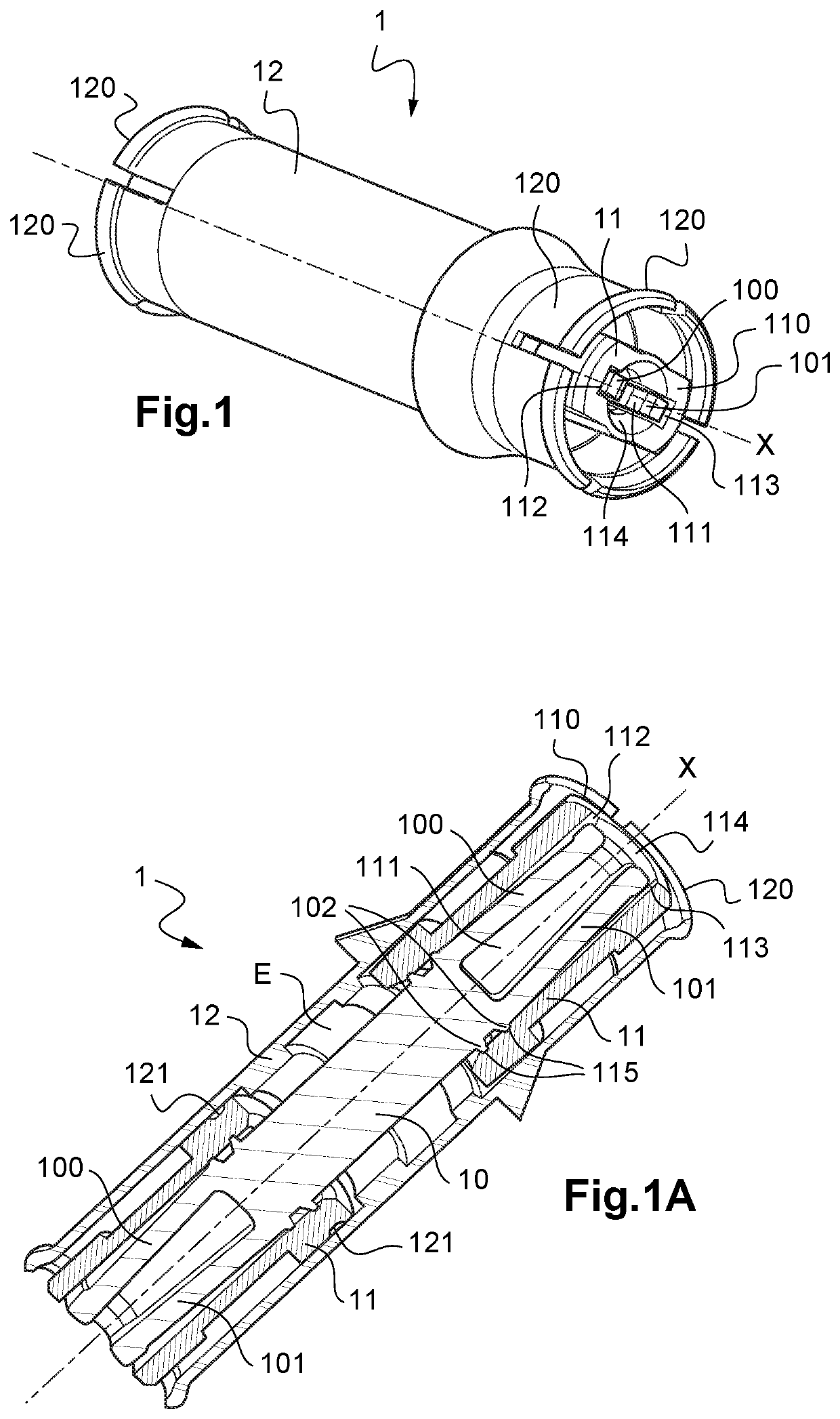
[0057]FIG. 1 is a perspective view of a RF connector according to the invention, forming a coupling connection;

[0058]FIG. 1A is a longitudinal cross-sectional view of the connector according to FIG. 1;

[0059]FIG. 1B is a detail view of one end of the connector according to FIGS. 1 and 1A;

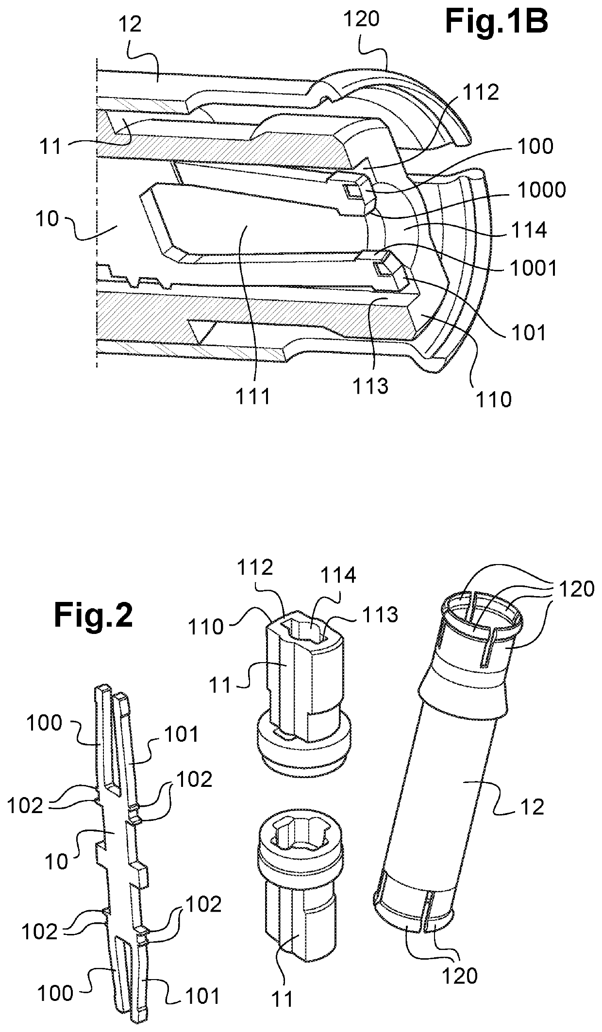
[0060]FIG. 2 shows in perspective views all the components of the RF connector according to FIGS. 1 to 1B;

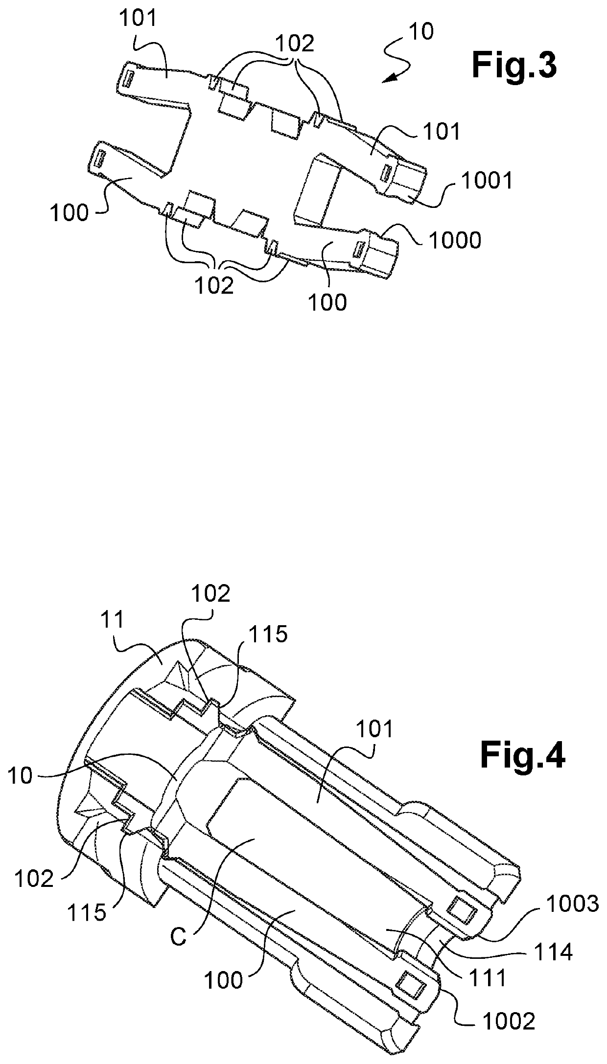
[0061]FIG. 3 is a perspective view of a flat central contact according to the invention;

[0062]FIG. 4 is a longitudinal cross-sectional view of a variant of a connector according to the invention;

[0063]FIG. 5 is a longitudinal cross-sectional view of an exemplary connection assembly, intended to link two printed circuit boards comprising two r...


PUM


Abstract

The application relates to a connector, intended to transmit radio frequency RF signals, of longitudinal axis X, including: a central contact under the form of an elongated flat strip which at least one of its ends is shaped as a fork with two flexible branches to define inwardly a cavity extending along the axis X for receiving a contact pin of one complementary connector, the two flexible branches of the fork being configured such that to apply a contact force to the contact pin; at least one solid insulating structure in which the central contact is mechanically retained, one of its ends of the insulating structure being configured to let the two flexible branches to move freely radially and to guide the contact pin while enabling its swivelling when inserted into the cavity (C) defined by the fork.

Description

TECHNICAL FIELD[0001]The present invention relates to a connector, intended in particular to transmit radio frequency RF signals.[0002]In the framework of the invention the term “connector” includes a plug or jack, a receptacle, an adaptor as well as a bullet.[0003]The applications particularly targeted by the invention are the connection of telecommunication equipment such as base transceiver stations BTS, RRU / RRH (remote radio unit / remote radio head) units and distributed antenna system for the wireless communications market.[0004]The invention also relates generally to the connectors in the medical domain, the industrial domain, the aeronautical domain, the transport domain and the space domain.[0005]The connectors according to the invention can be used in particular to link two parallel printed circuit boards, usually called a board-to-board connecting system or even a printed circuit board to another component such as a module, a filter or a power amplifier or an antenna.[0006]...

Claims


Application Information

Patent Timeline
Patent Type & Authority Patents(United States)
IPC IPC(8): H01R13/11H01R13/646H01R13/631
CPCH01R13/112H01R13/631H01R13/646H01R2201/16H01R12/91H01R24/50H01R24/542H01R24/44H01R12/73H01R13/41H01R12/7082H01R2103/00H01R13/15
Inventor XIE, GUANGRONGYUAN, KAIYANG
Owner RADIALL SA
Features
  • R&D
  • Intellectual Property
  • Life Sciences
  • Materials
  • Tech Scout
  • Unparalleled Data Quality
  • Higher Quality Content
  • 60% Fewer Hallucinations
Learn More