[0008] Objects of the invention include a fuel cell power plant that efficiently and properly removes the product and
proton drag water from the cathode, thereby ensuring that the maximum amount of
oxygen from the oxidant reactant gas stream reaches and reacts with the catalyst on the cathode side of the MEA.
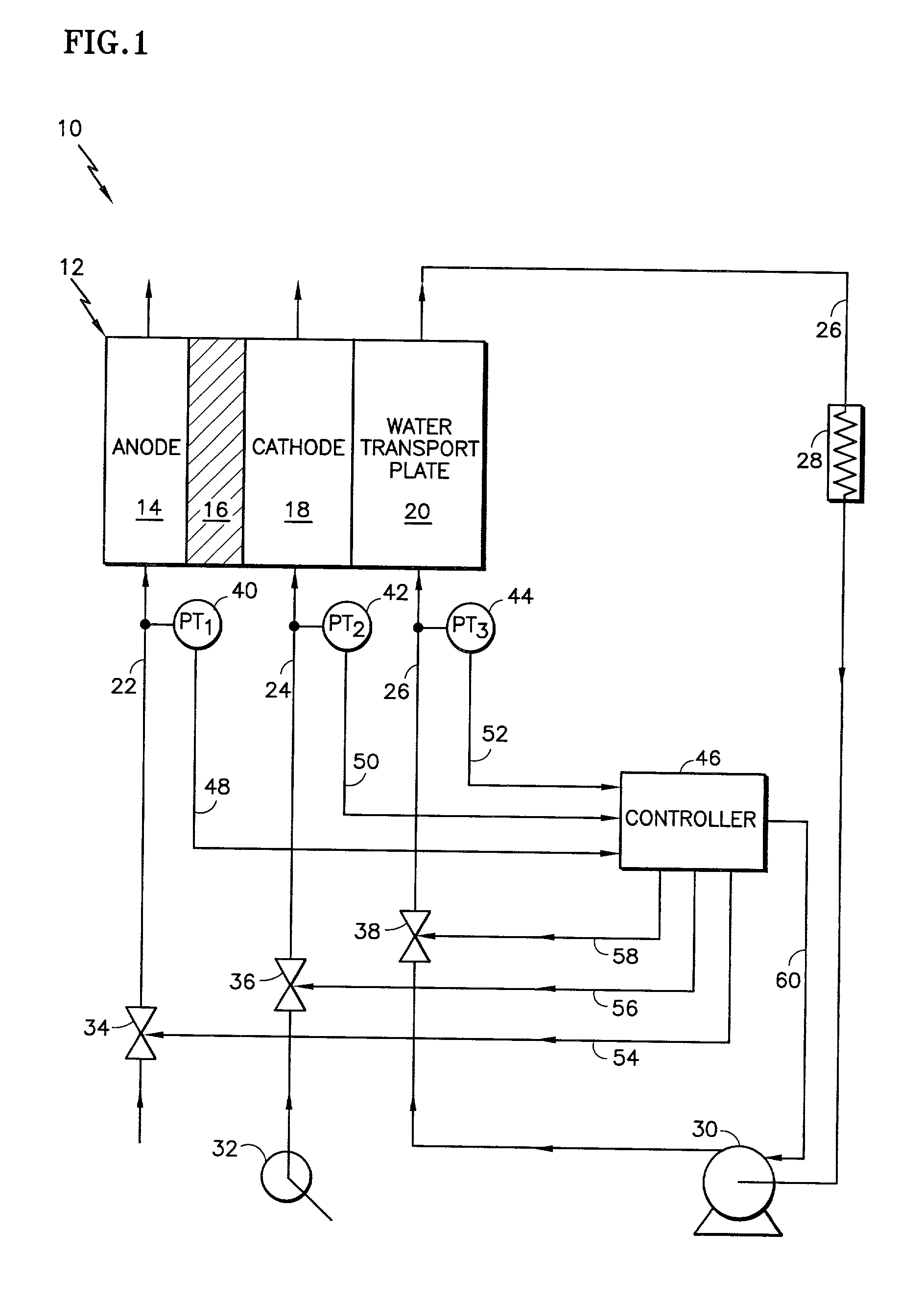
[0009] The present invention is a fuel cell power plant that includes a fuel cell having a
membrane electrode assembly (MEA), which is disposed between an anode support plate and a cathode support plate and wherein the anode and / or cathode support plates include a hydrophilic substrate layer. The fuel cell power plant also includes a fuel reactant gas stream, which is in fluid communication with the anode support plate's hydrophilic substrate layer, and an oxidant reactant gas stream, which is in fluid communication with the cathode support plate's hydrophilic substrate layer, and a cooling water stream, which is in fluid communication with both the anode and cathode support plate hydrophilic substrate
layers. The hydrophilic substrate layer in the anode support plate enhances the migration of the cooling water to the anode side of the MEA, and the hydrophilic substrate layer in the cathode support plate improves the removal of water from the cathode side of the MEA. The hydrophilic substrate
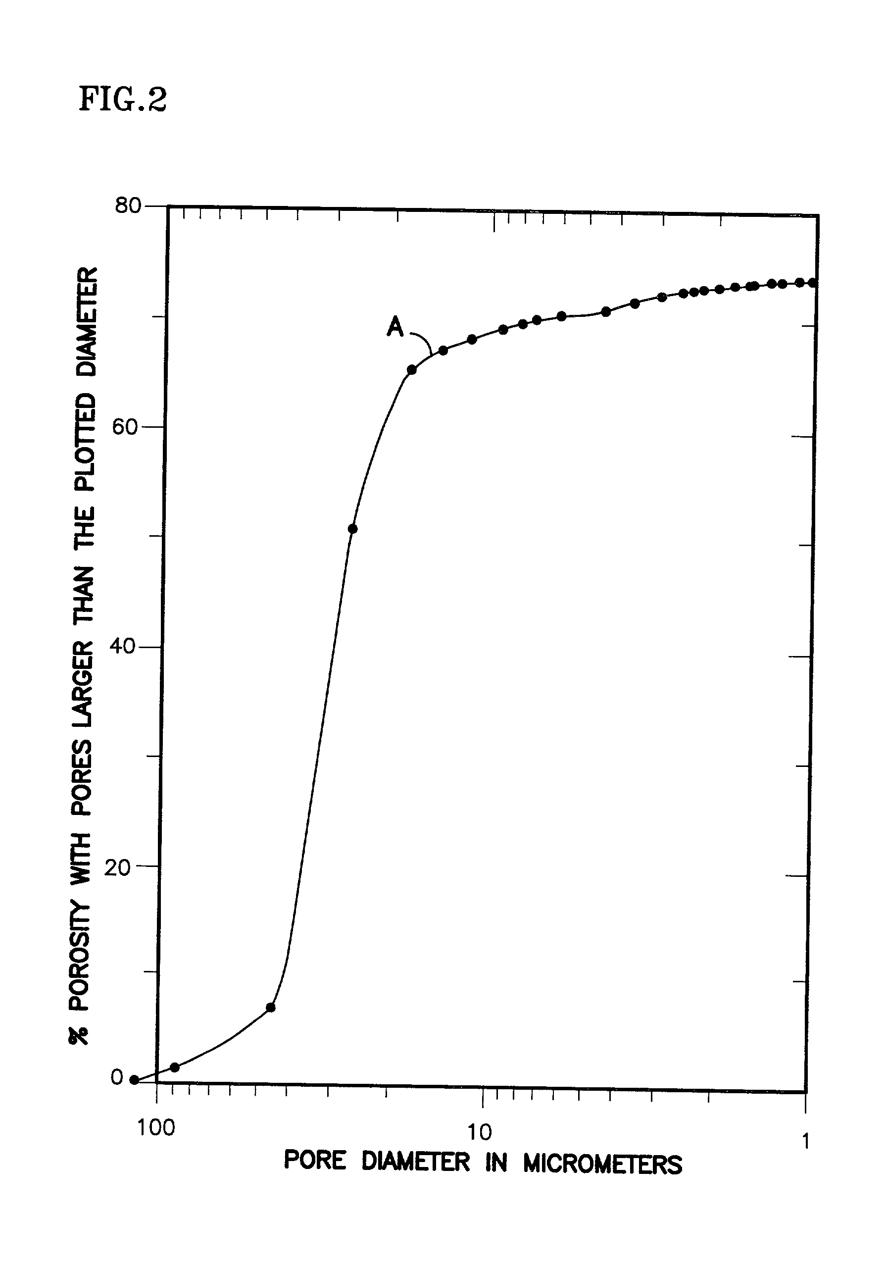
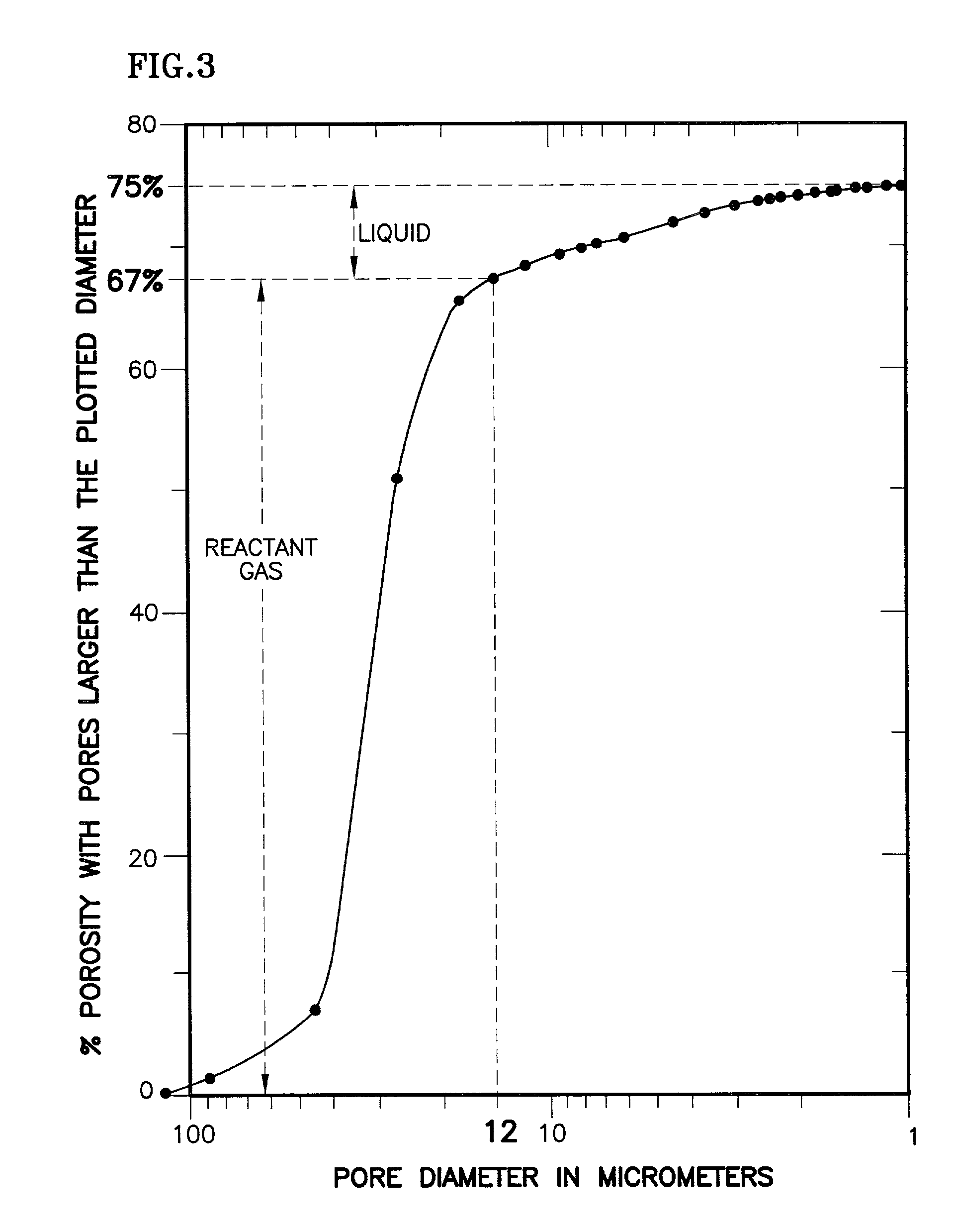
layers within both the anode and cathode support plates have a predetermined level of
porosity (i.e., number of pores) and pore size. The inventors of the present invention recognized that without controlling the number of pores within the hydrophilic substrate that contain water, the water will fill 100% of the available pores, thereby preventing any migration of the reactant gases. The inventors of the present invention, therefore, recognized that controlling the pressure of the reactant gas streams and the coolant stream, controls the percentage of pores that contains water or reactant gas. The present invention utilizes a pressure differential between the coolant stream and the reactant gas streams to control the respective distribution of the streams within the pores of a hydrophilic substrate. The pressure differential is established such that a greater percentage of the pores within the hydrophilic substrate layer contain reactant gas rather than water. The present invention, therefore, provides a means for creating a pressure differential between the reactant gas streams and the coolant stream such that the pressure of the reactant gas streams is greater than the pressure of the coolant stream. Operating the fuel cell at such pressure differential ensures that the product and
proton drag water that form at the
cathode catalyst layer will migrate through the cathode support plate and away from the MEA. Controlling the coolant and fuel reactant gas streams on the anode side of the MEA also ensures that the cooling water will continually migrate from the coolant stream toward the anode side of the MEA, thereby preventing the membrane from becoming dry.
[0010] Proper
water balance in the cathode and anode support plates ensures that the PEM remains moist, thereby prolonging the fuel cell's life, as well as improving its
electrical efficiency. Proper water removal also facilitates increased
oxygen utilization within the fuel cell. Specifically, without proper water removal, a reduced portion of the available oxygen reaches the catalyst. Increasing the amount of oxygen that is available at the catalyst increases the fuel cell's performance and / or reduces the overall size of the fuel cell in order to generate a certain
power rating. Although U.S. Pat. No. 5,641,586 recognized that replacing the cathode hydrophobic substrate layer with a hydrophilic substrate layer increased the
cell voltage, that patent failed to discuss the importance of water removal from the cathode. Moreover, that patent failed to teach that controlling the pressure of the reactant gas streams and the coolant streams controls the filled
porosity of the hydrophilic substrate, as well as reducing the
water content of the catalyst layers. The present invention, in contrast, provides a means for preventing the cathode support plate from flooding, thereby ensuring that the maximum amount of oxidant reactant gas reaches the cathode side of the MEA. Hence the present invention not only improves the electrical
power output capacity of a fuel cell but also increases the fuel cell's oxygen utilization, which, in turn, further improves the fuel
cell system's operational efficiency.
[0012] In another embodiment of the present invention, the water transport plates include interdigitated passageways (i.e., flow channels) in lieu of conventional passageways for the reactant gas streams to pass therethrough. Interdigitated passageways shall mean at least two distinct passageways separated by a dividing wall (i.e., rib) such that the reactant gas stream enters one distinct passageway (i.e., entry passageway) and exits the other distinct passageway (i.e., exit passageway). In order for the reactant gas stream to migrate from the entry passageway to the exit passageway, the reactant gas stream passes through the anode and cathode support plates, thereby increasing the
mass transfer of the reactant gas streams to the anode and cathode support plates. Increasing the quantity of reactant gases that reach the catalysts, in turn, increases the
electrical performance of the fuel cell. Hence, utilizing interdigitated flow channels in lieu of conventional flow channels within a porous water transport plate increases the
electrical performance of the fuel cell while maintaining an efficient
water management system.
[0015] In a further embodiment of the present invention, a fuel cell has an anode and / or cathode support plate that includes a hydrophilic substrate layer but does not include a
diffusion layer. Removing the anode
diffusion layer or reducing its thickness increases the migration of water from the water transport plate to the MEA, thereby ensuring proper moisturizing of the PEM, particularly at
high current densities, which in turn, further improves the
electrical efficiency of the fuel cell. Removing the cathode
diffusion layer or reducing its thickness reduces the distance through which the oxidant reactant gas must pass before reaching the catalyst, thereby increasing the fuel cell's oxygen utilization characteristics.

