Power supply control device and method
a control device and power supply technology, applied in the direction of process and machine control, pulse technique, instruments, etc., can solve the problems of large packaging space, poor response of microcomputer basis control to such abnormal current, and failure to opera
- Summary
- Abstract
- Description
- Claims
- Application Information
AI Technical Summary
Benefits of technology
Problems solved by technology
Method used
Image
Examples
first embodiment
[0048] First Embodiment
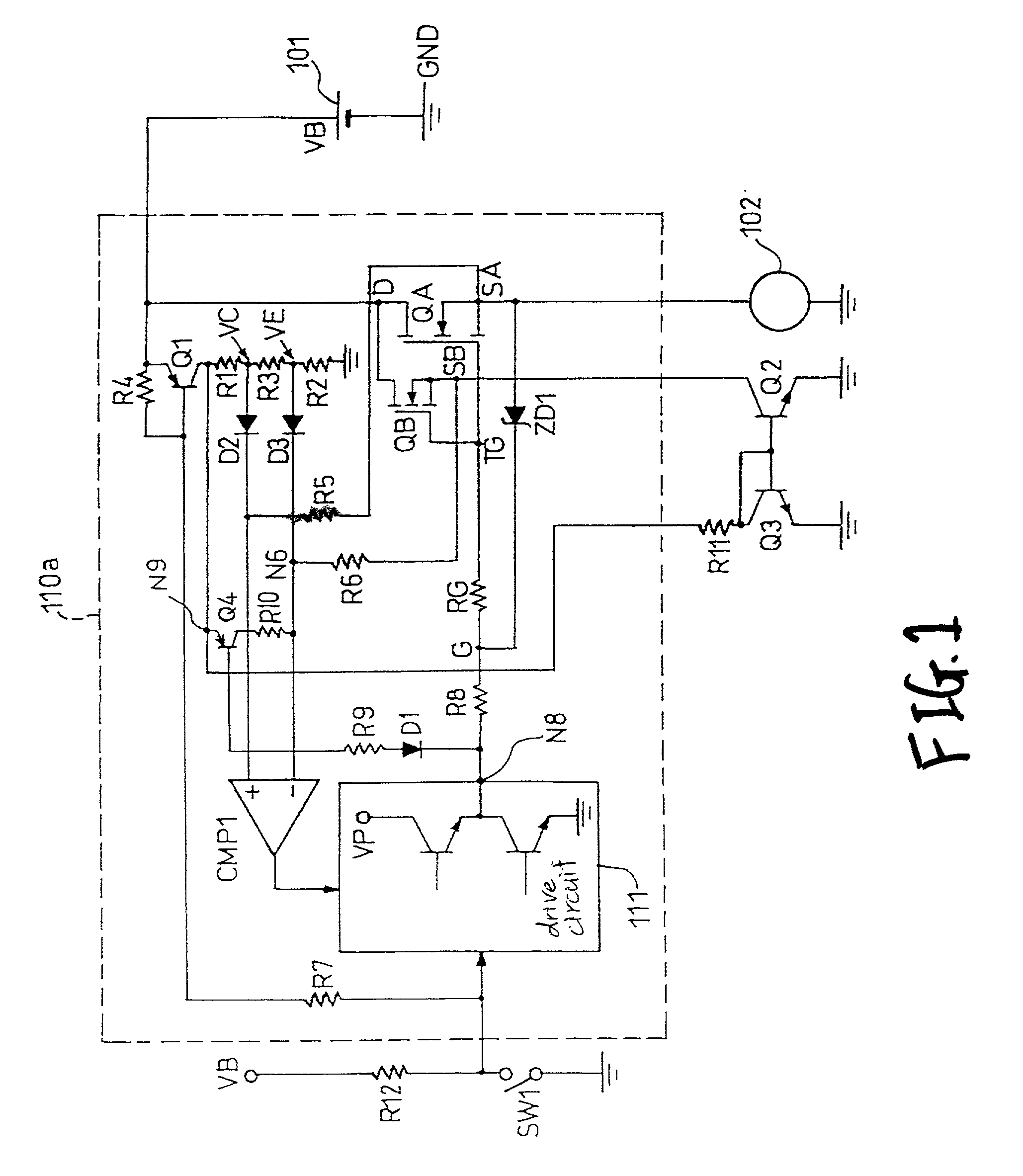
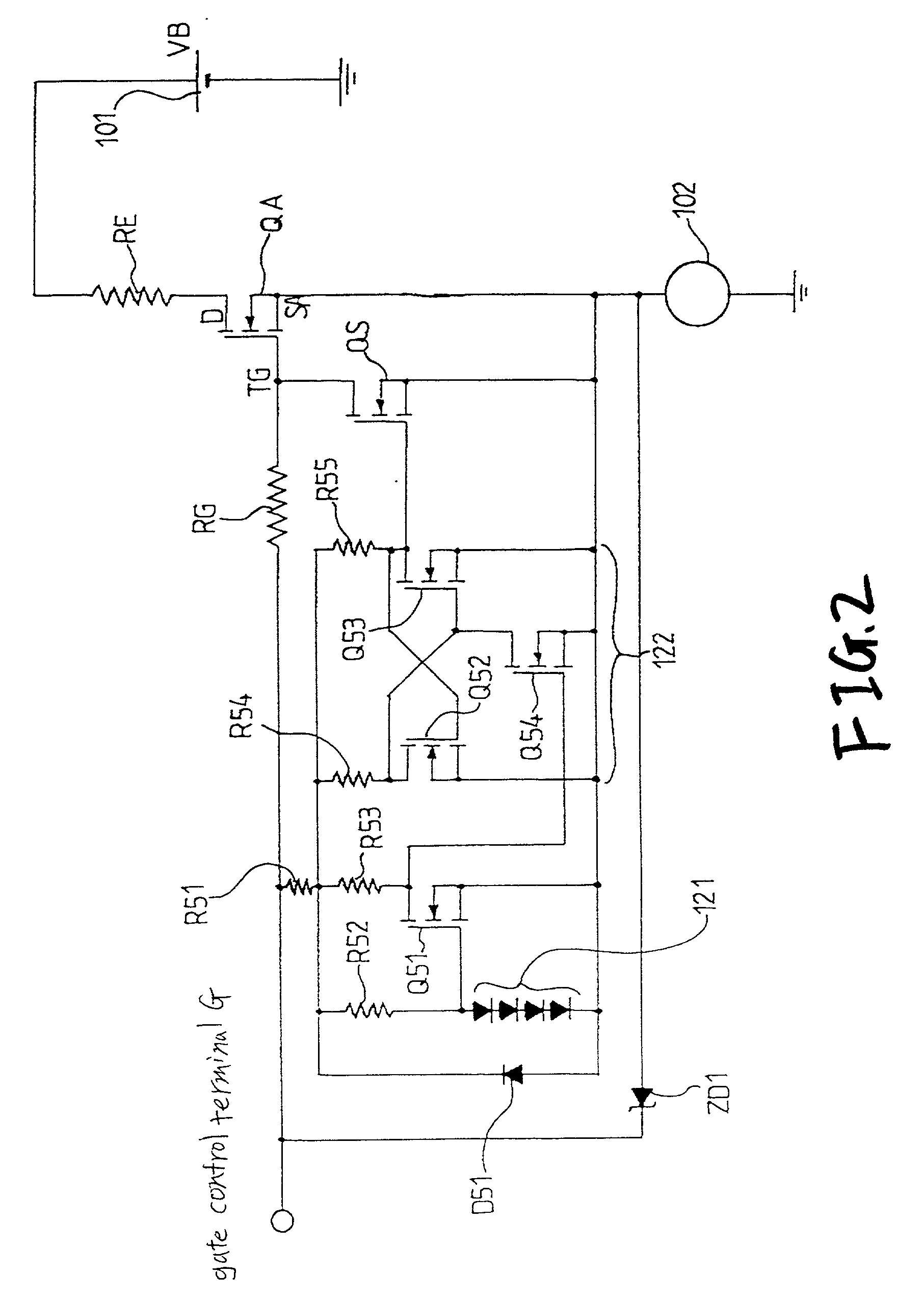
[0049] A power supply control device, which forms a first embodiment of the present invention, will be described in accordance with FIG. 1. The power supply control device is arranged such that a drain (D)--source (SA) path of a main control FET QA as a semiconductor switch is inserted in a series fashion in a path for supplying an output voltage VB of a power supply 101 to a load 102. In this instance, the main control FET QA is an NMOS FET having a DMOS structure. If required, it may be a PMOS FET.
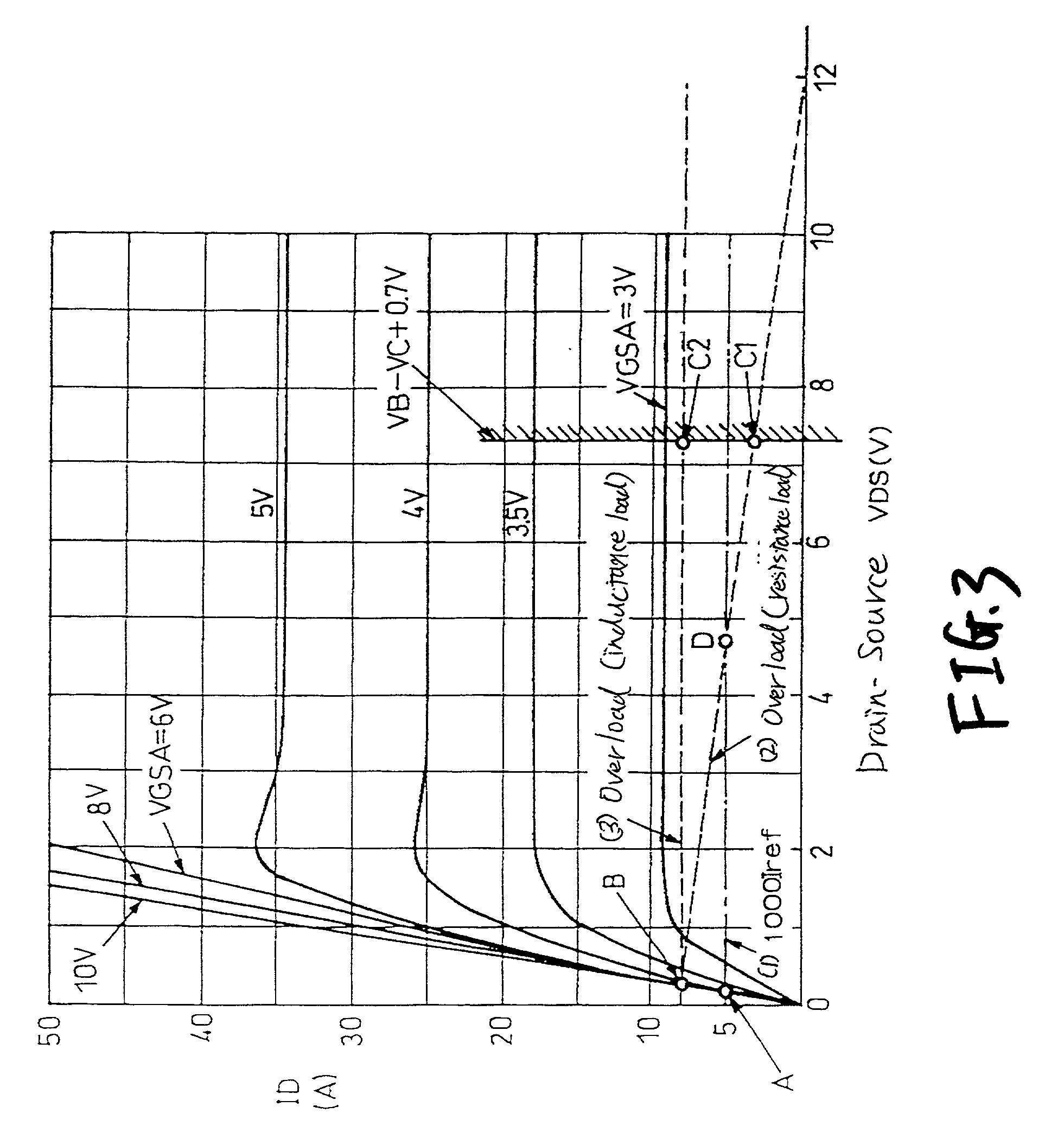
[0050] In the figure, a circuit section for driving and controlling the main control FET QA includes a reference FET (second semiconductor switch) QB, resistors R1 to R12, and RG, a Zener diode ZD1, diodes D1 to D3, transistors Q1 to Q4, a comparator CMP1, a drive circuit 111, and a switch SW1. In the specification description to follow and the accompanying drawings attached thereto, the resistors are denoted as R followed by reference numerals and characters. Thos...
second embodiment
[0100] Second Embodiment
[0101] A power supply control device and method, which forms a second embodiment of the present invention, will be described with reference to FIG. 5. The power supply control device of the embodiment is characteristically featured in that the Reference current generating device is constructed as a constant current source. Specifically, difference of the circuit arrangement (FIG. 1) of the power supply control device of the first embodiment is that a resistor R13 is inserted between the resistor R11 and the collector of the transistor Q1 in the Reference current generating device, and a Zener diode ZD2 is connected between the other end of the resistor R13 and ground potential. In FIG. 5, a circuit section 110b enclosed with a dotted line indicates a circuit section to be analog integrated onto a chip (this section will be referred to a chip-circuitry section).
[0102] In the circuit arrangement, the collector current IC (Q3) is given by
IC(Q3)={VZD2-(on-voltage...
first modification
[0107] First Modification
[0108] The first modification is characteristically featured in that a inrush current mask circuit 105 as shown in FIG. 6 is additionally used to the circuit arrangement (FIG. 1 or 5) of the power supply control device of the first or second embodiment.
[0109] When the load 102 (e.g., head lights) is turned on, in rush current flows, which is several to several tens times as large as a normal current in amplitude. The period that the inrush current flows depends on the type and capacity of the load 102, but is about 3 msec to 20 msec. If the overcurrent control as described in the first or second embodiment is carried out during the surge-current flowing period, some time is taken till the load is settled down into a stationary state. As a result, the response of the load per se delays sometimes. Specifically, the headlights are delayed in lighting. The embodiment solves this problem by adding the inrush current mask circuit 105 (corresponding to prohibiting ...
PUM
 Abstract
Description
Claims
Application Information
 - R&D
- Intellectual Property
- Life Sciences
- Materials
- Tech Scout
- Unparalleled Data Quality
- Higher Quality Content
- 60% Fewer Hallucinations
Browse by: Latest US Patents, China's latest patents, Technical Efficacy Thesaurus, Application Domain, Technology Topic, Popular Technical Reports.
© 2025 PatSnap. All rights reserved.Legal|Privacy policy|Modern Slavery Act Transparency Statement|Sitemap|About US| Contact US: help@patsnap.com


