Methods for the regenertion of a denitration catalyst

a denitration catalyst and catalyst technology, applied in the field of denitration catalyst regeneration methods, can solve the problems of reduced catalytic power, low regenerative effect of conventional cleaning methods using water or hydrochloric acid,

Inactive Publication Date: 2001-08-09
MITSUBISHI HITACHIPOWER SYST LTD
View PDF0 Cites 23 Cited by
  • Summary
  • Abstract
  • Description
  • Claims
  • Application Information

AI Technical Summary

Benefits of technology

0017] Conventionally, catalysts having arsenic compounds deposited thereon have been incapable of regeneration and hence disposed of. However, the re

Problems solved by technology

This calcium sulfate covers the catalyst surfaces and hinders NO and NH.sub.3 gases from diffusing into the interior of the catalyst, resulting in reduced catalytic power.
For this reason, there has been a problem in that, when the substances res

Method used


Image

  • Methods for the regenertion of a denitration catalyst

Examples


example 2

[0059] Denitration catalysts (composed of 89.2 wt. % of TiO.sub.2, 10.2 wt. % of WO.sub.3, and 0.6 wt. % of V.sub.2O.sub.5) having a honeycomb configuration with a pitch of 7.4 mm were used in a coal-fired boiler plant B for about 55,000 hours.

[0060] In order to regenerate twelve denitration catalysts having reduced denitration power as a result of the aforesaid use, each of them was soaked in a cleaning fluid comprising a 5% aqueous solution of NaOH, KOH or Na.sub.2CO.sub.3 so that the volume ratio of the cleaning fluid to the denitration catalyst was 4.0, allowed to stand at 60.degree. C. for 4 hours, washed with water, and then dried.

[0061] After the above-described alkali cleaning, the catalyst was soaked in an activating fluid comprising a 5 wt. % aqueous solution of HCl, HNO.sub.3, H.sub.2SO.sub.4 or HF so that the volume ratio of the activating fluid to the catalyst was 4.0, allowed to stand at 40.degree. C. for 30 minutes, washed with water, and then dried. As shown in Table...

example 3

[0066] The unused catalysts and spent catalysts for coal-fired boiler plants A and B, the regenerated catalysts obtained in Examples 1 and 2, and the regenerated catalysts obtained in Comparative Examples 1 and 2 were comparatively tested for denitration power under the conditions shown in Table 1.

[0067] Moreover, with respect to each of the regenerated catalysts, its average arsenic content and its compressive strength were also measured.

[0068] The results thus obtained are shown in Tables 2 and 3. In Tables 2 and 3, the degree of denitration (%) and the compressive strength ratio are defined as follows.

[0069] Degree of denitration (%)={[(Inlet NO.sub.x content) -(Outlet NO.sub.x content)] / (Inlet NO.sub.x content)}.times.100

[0070] Compressive strength ratio=(Compressive strength of test sample) / (Compressive strength of unused catalyst)

1 TABLE 1 Test sample Item Catalyst for coal-fired boilers Shape of catalyst 46 mm .times. 53 mm .times. 800 mm(L) Flow rate of gas 20.2 Nm.sup.3 / m.s...

example 4

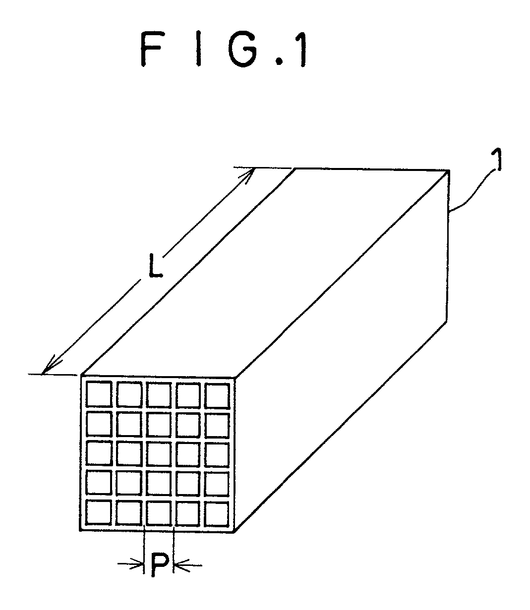
[0075] Denitration catalysts (composed of 89.2 wt. % of TiO.sub.2, 10.2 wt. % of WO.sub.3, and 0.6 wt. % of V.sub.2O.sub.5) having a honeycomb configuration with a pitch of 7.4 mm as shown in FIG. 1 were used in exhaust gas from a coal-fired boiler plant A for about 23,000 hours.

[0076] In order to regenerate six denitration catalysts having reduced denitration power as a result of the aforesaid use, each of them was soaked in a cleaning fluid comprising an aqueous solution containing H.sub.2SO.sub.4 at a concentration of 0.03%, 0.05%, 0.3%, 1%, 20% or 30% so that the volume ratio of the cleaning fluid to the denitration catalyst was 4.0, allowed to stand at 20.degree. C. for 4 hours, washed with water, and then dried.

[0077] The regenerated catalysts thus obtained are referred to as "Catalysts 101-106" in order of increasing sulfuric acid concentration.

[0078] Moreover, in order to regenerate five other denitration catalysts having reduced denitration power as a result of the aforesai...


PUM

PropertyMeasurementUnit
Angleaaaaaaaaaa
Angleaaaaaaaaaa
Percent by massaaaaaaaaaa

Abstract

This invention provides a method for the regeneration of a denitration catalyst which comprises cleaning a denitration catalyst having reduced denitration power with an aqueous alkaline solution to remove the substances deposited thereon, and subjecting the catalyst to an activation treatment with an aqueous acid solution; a method for the regeneration of a denitration catalyst which comprises cleaning a denitration catalyst having reduced denitration power with a cleaning fluid comprising an aqueous solution containing sulfuric acid or ammonia at a concentration of 0.05 to 20% by weight and maintained at a temperature of 10 to 90°C.; and a method for the regeneration of a denitration catalyst which comprises cleaning a denitration catalyst having reduced denitration power under the above-described conditions, and impregnating the denitration catalyst with a catalytically active component so as to support it on the catalyst.

Description

FIELD OF THE INVENTION AND RELATED ART STATEMENT[0001] This invention relates to methods for the regeneration of a denitration catalyst. More particularly, it relates to methods for the regeneration of a denitration catalyst which makes it possible to regenerate a denitration catalyst having reduced denitration powder and considered to be hard to regenerate, and thereby utilize it again effectively.[0002] Recently, in order to remove nitrogen oxides (hereinafter referred to as NO.sub.x) produced in boilers and various combustion furnaces for the purpose of preventing air pollution, a catalytic ammonia reduction process wherein ammonia is used as a reducing agent and nitrogen oxides are decomposed to nitrogen and water by contact with a catalyst is being widely employed. Most of the NO.sub.x removal catalysts currently used for practical purposes are honeycomb-shaped catalysts which have through-holes of square cross section in order to prevent clogging with dust present in exhaust g...

Claims


Application Information

Patent Timeline
IPC IPC(8): B01D53/86B01D53/96B01J23/92B01J38/60B01J38/62B01J38/64B01J38/66B01J38/68
CPCB01D53/8625B01D53/96B01J23/92B01J38/60B01J38/62B01J38/64B01J38/66B01J38/68Y02C20/30
Inventor NOJIMA, SHIGERUIIDA, KOZO
Owner MITSUBISHI HITACHIPOWER SYST LTD
Why Eureka
Try Eureka