Optical system for miniature personal displays using reflective light valves

Inactive Publication Date: 2001-08-16
IBM CORP
View PDF0 Cites 22 Cited by
  • Summary
  • Abstract
  • Description
  • Claims
  • Application Information

AI Technical Summary

Benefits of technology

0019] The object of the present invention is to provide an optical

Problems solved by technology

The CRT-based systems are bulky, expensive, and heavy, and primarily used for military helmet-mounted applications.
This technology is not suitable for lightweight, compact personal displays.
Although appropriate for the low resolution displays currently available, such as sub-VGA to VGA (640.times.480 pixels), this transmission-based LC technology is not adequate for high resolution miniature portable displays.
Thus, the pixel size is only limited by the CMOS technology required to fabricate the drive circuitry, which today is less than 10 microns per pixel.
However, reflection-based light valves, such as liquid crystal (LC) spatial light modulators (SLMS) have complex illumination requirements.
A simple backlight structure typically used in transmission-based displays is not directly applicable for reflective SLMS.
The addition of light brightness enhancing polymer films improves the directionalit

Method used


Image

  • Optical system for miniature personal displays using reflective light valves
  • Optical system for miniature personal displays using reflective light valves
  • Optical system for miniature personal displays using reflective light valves

Examples


Example

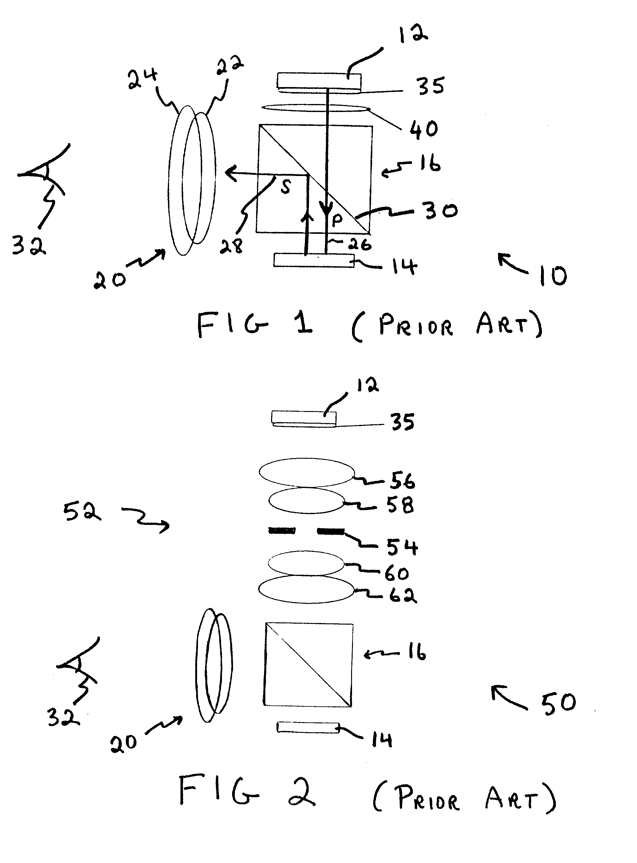
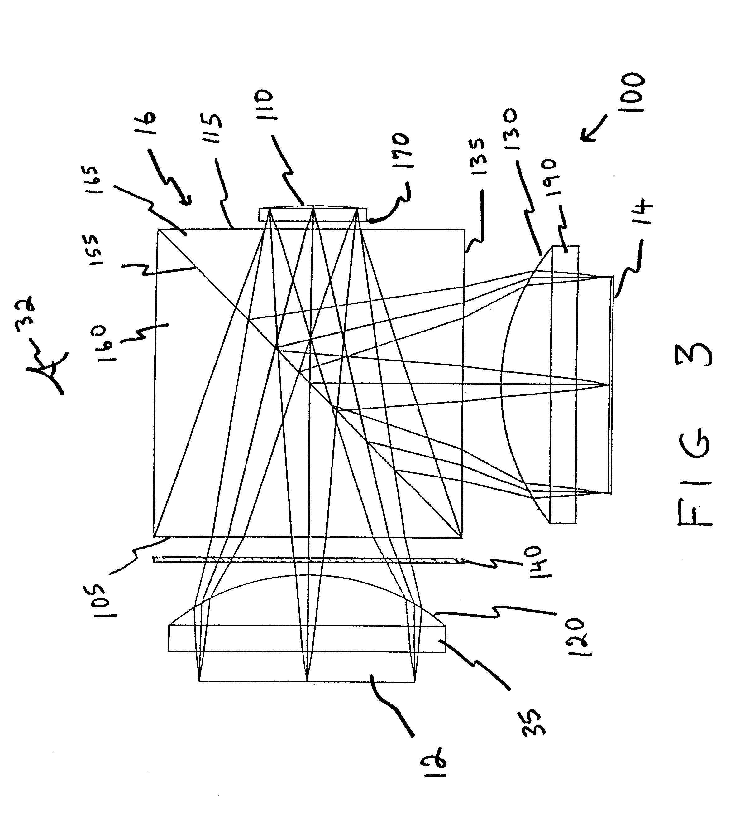
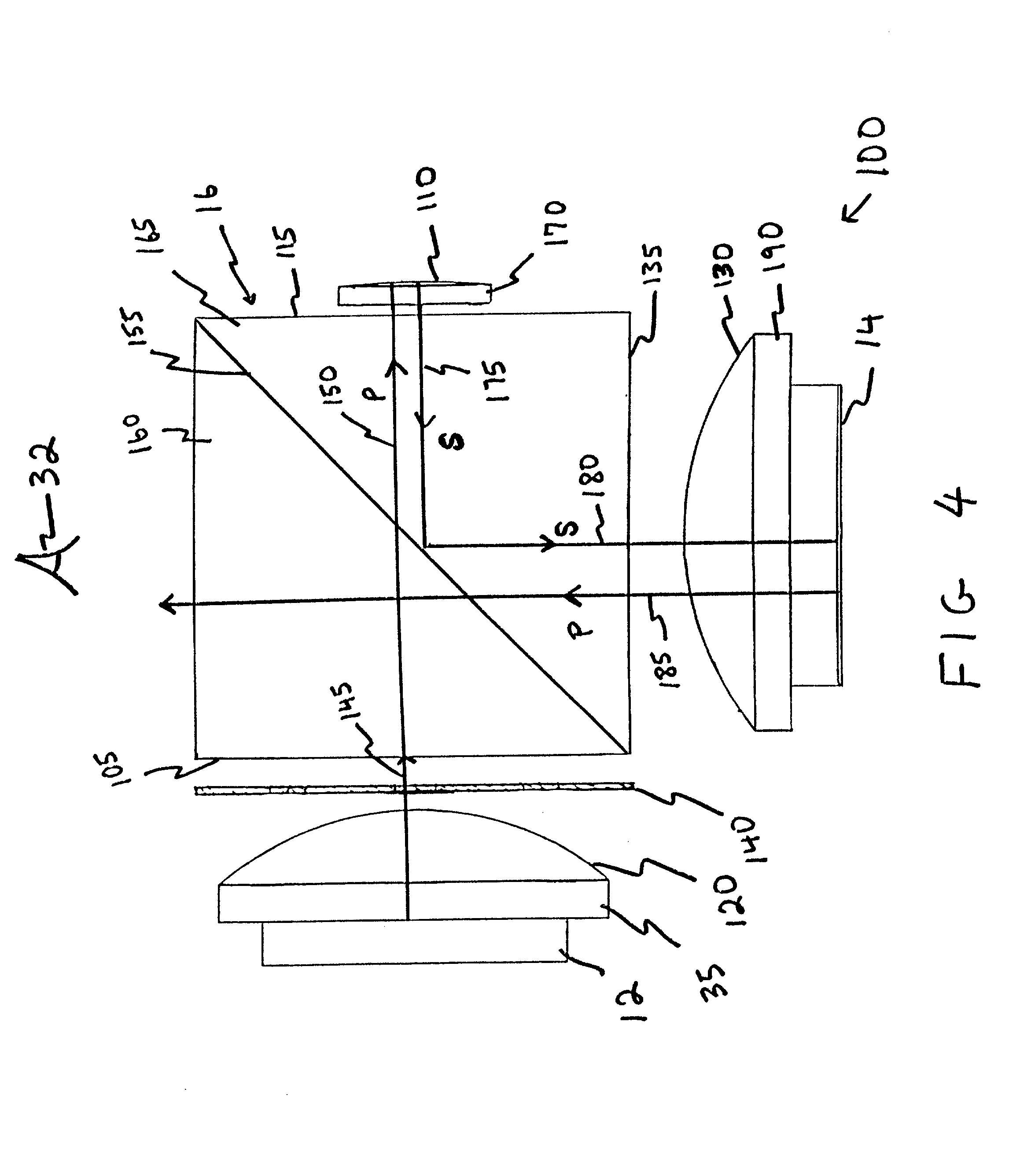
[0037] FIG. 3 shows one embodiment of an illumination system 100 suitable for compact portable displays having a reflective SLM 14. The illumination optics of the system 100 are compact but provide the full function as the conventional system 50 shown in FIG. 2. That is, the optics of the system 100 relay light from a light source, such as the backlight source 12, onto the SLM 14. In addition, the optics of the system 100 provide an aperture stop to limit the numerical aperture of the system 100. The compact nature of the illumination system 100 is derived from folding the optical path almost entirely within the PBS 16. The individual optical elements are placed on three surfaces of the PBS 16.

[0038] The illumination optical relay system 100 comprises a light source, such as the backlight 12 for providing light, and a PBS 16 having a first surface 105, which is an input surface that receives light from the backlight 12. The first PBS surface 105 is referred to as an input surface. I...


PUM


Abstract

An illumination system and display are disclosed that include a light for providing light, a polarizing beam splitter (PBS) having a first surface that receives the light from the backlight. The PBS passes a first polarization of the received light to a curved mirror located at a second PBS face, which second PBS face is opposite the first PBS face. The curvature of the mirror provides the optical power necessary for proper imaging, while limiting the reflecting area of the mirror provides an aperture stop that determines the numerical aperture of the optical system. The display also includes a quarter wave plate and a spatial light modulator (SLM). The quarter wave plate is located between the PBS and mirror and changes the first polarization of light, directed from the PBS to the mirror, to a second polarization which is reflected from the mirror back to the PBS. The SLM receives this second polarization of light after reflection thereof by the PBS, and selectively rotates the second polarization of light to form an image forming light having the first polarization, which is reflected back to the PBS. Through an exit face, the PBS provides the rotated image forming light to a viewer. Between the viewer and the PBS exit surface, an imaging lens system is provided that includes at least one folding mirror.

Description

BACKGROUND OF THE INVENTION[0001] 1. Field of the Invention[0002] The present invention is directed to an optical system for illuminating and imaging a reflective light valve, and more particularly, to systems using compact lightweight, and foldable optics for personal miniature displays using reflective light valves.[0003] 2. Discussion of the Prior Art[0004] Typically, conventional miniature displays, such as head mounted displays (HMDs), are based on miniature cathode ray tube (CRT) or transmission-based liquid crystal light valve technology. The CRT-based systems are bulky, expensive, and heavy, and primarily used for military helmet-mounted applications. This technology is not suitable for lightweight, compact personal displays.[0005] Transmission-based liquid crystal (LC) technology is the preferred technology for these portable miniature displays today. Although appropriate for the low resolution displays currently available, such as sub-VGA to VGA (640.times.480 pixels), thi...

Claims


Application Information

Patent Timeline
IPC IPC(8): G02B5/30G02B27/01
CPCG02B5/30G02B27/0172
Inventor DOANY, FUAD ELIASSINGH, RAMA NAND
Owner IBM CORP
Why Eureka
Try Eureka