Porous electrode wire for use in electrical discharge machining and method of manufacturing the same

a technology of porous electrode wire and electrical discharge machining, which is applied in the field of electro-electrode wire, can solve the problems of low mechanical strength, many deficiencies, and inferior machining accuracy and tenancy of wire breakage, and achieves the effect of improving machining accuracy and tenancy

Inactive Publication Date: 2001-08-16
SEONG KI CHUL
View PDF0 Cites 13 Cited by
  • Summary
  • Abstract
  • Description
  • Claims
  • Application Information

AI Technical Summary

Problems solved by technology

However, it revealed many deficiencies mainly due to its low mechanical strength.
For example, high tensile strength could not be applied to the copper wire during the machining so that vibration of the wire can not be controlled, resulting in an inferior machining accuracy and tenancy of wire breakage.
Moreover, machining speed was relatively slow.
However, in that case, drawing process .sup.tp form a wire becomes difficult because of the presence of a brittle phase in the alloy.
Thus, the improvement was limited to the nature of the coating metal.
Further, the porous nature of the wire arises from the cracks in the alloy layer and the coating layer during the drawing step.

Method used


Image

  • Porous electrode wire for use in electrical discharge machining and method of manufacturing the same
  • Porous electrode wire for use in electrical discharge machining and method of manufacturing the same
  • Porous electrode wire for use in electrical discharge machining and method of manufacturing the same

Examples


Embodiment Construction

1

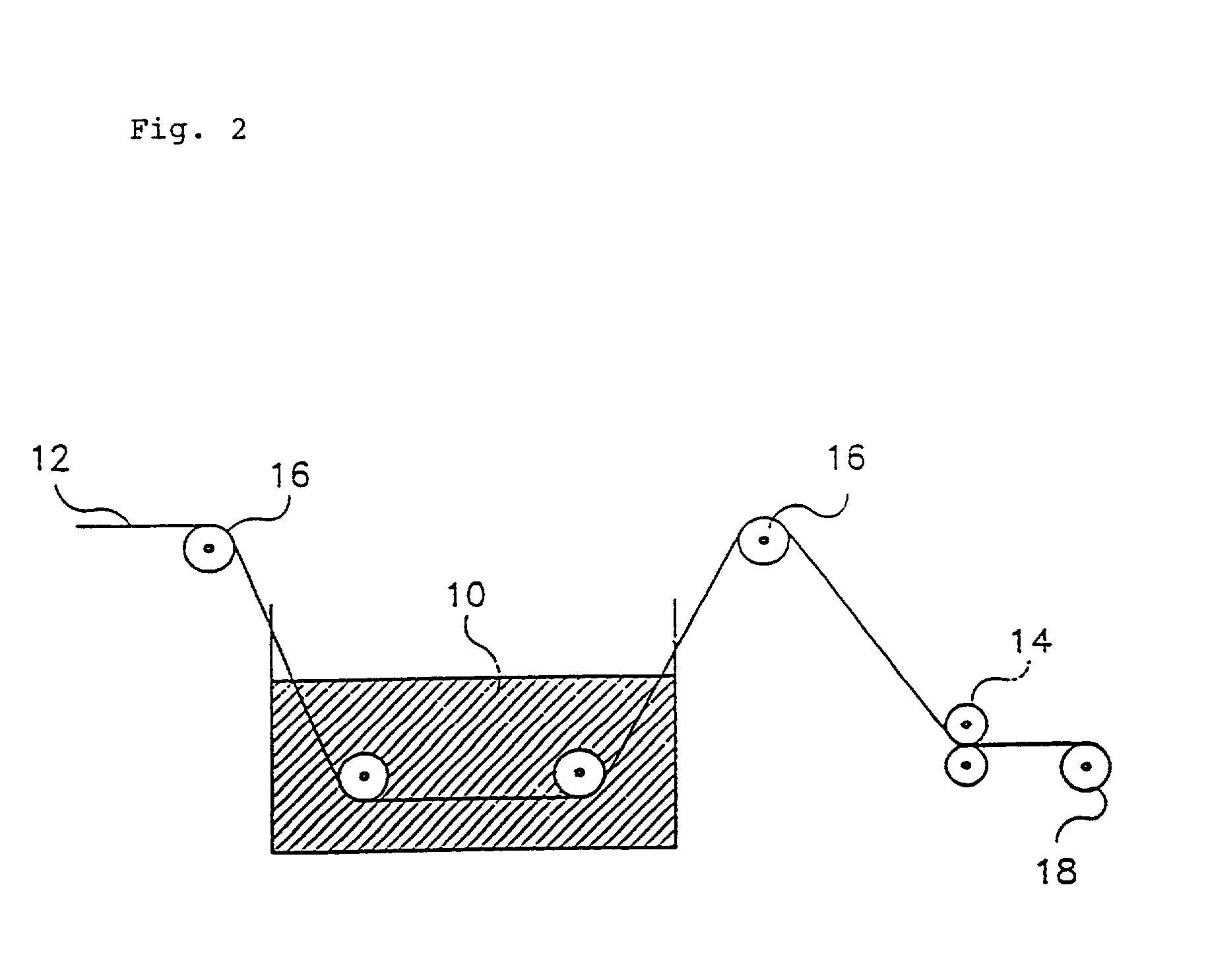
[0039] A brass wire having 63-67 wt % copper and 33-37 wt % zinc is prepared as a core wire of an intermediate diameter. Hot dip galvanizing is practiced on the core wire to form a coating layer. The hot dip galvanizing may use zinc, aluminium, tin or the alloy and particularly, zinc is preferred. According to a conventional hot dip galvanizing process, the core wire undergoes pre-treatment of alkali degrease and acid cleaning. Then, it passes ammonium chloride flux bath. Subsequently, the core wire passes a molten bath of zinc. At this time, the temperature of the bath is maintained 400-500.degree. C. and the core wire is coated for about 1-10 seconds to form a zinc coating layer and a copper-zinc alloy layer. The alloy layer is formed by a diffusion reaction between the core and the zinc and the coating layer of zinc is formed thereon. Further the alloy layer is the hardest layer among others and has lower elongation than the core.

[0040] Thus, an copper-zinc alloy layer of 1-2 m ...


PUM

PropertyMeasurementUnit
thicknessaaaaaaaaaa
diameteraaaaaaaaaa
temperatureaaaaaaaaaa

Abstract

The present invention relates to a porous electrode wire for use in electrical discharge machining and the method of manufacturing the same. The wire improves the machining speed at least 15% compared with a conventional zinc coated wire, which results from an increased cooling ability of the wire with a cooling liquid because of the increase in the surface area of the wire having porous surface morphology. Since the surface of the porous wire presents uniform profile of outer periphery rather than surface protrusions, it does not affect machining accuracy. Further, the porous nature of the wire is expected to improve flushability during the electrical discharge machining, providing spaces to eliminate particles of the machining. Therefore, in accordance with the method of the present invention, a zinc coated wire having improved performance of machining speed and flushability compared with a conventional coated wire can be provided without additional processes.

Description

BACK GROUND OF THE INVENTION[0001] 1. Field of the Invention[0002] The present invention relates to an electrode wire for use in electrical discharge machining and the method of manufacturing the same, particularly to a porous electrode wire having an improved machining speed and the method of manufacturing the same.[0003] 2. Description of the Background Art[0004] FIG. 1 represents a schematic drawing of a wire electrical discharge machine. An electrode wire is inserted through a start hole (7) of a workpiece (1), which is continuously fed through the hole. A high frequency voltage is applied between the wire (2) and the inside of the hole (7) to initiate an arc discharge between them. Then, machining the workpiece (1) to a desired shape can be achieved by melting the workpiece during the arc discharge and by removing the machining particles using a machining liquid and an instantaneous vaporization power between the wire and the workpiece. In accordance with the machining principl...

Claims


Application Information

Patent Timeline
Patent Type & Authority Applications(United States)
IPC IPC(8): B23H1/00B21C37/04B23H1/04B23H7/08B23H7/22B23K35/02C23C2/06C23C2/08C23C2/12C23C2/26C23C2/28C23C2/38C23C10/28C23C28/02
CPCB21C37/042B21C37/045B23H7/08C23C28/023C23C28/025Y10S428/939Y10S428/926C23C28/028Y10T428/12903Y10T428/12715Y10T428/12479Y10T428/12792Y10T428/12458Y10T428/12396Y10T428/1275Y10T428/12694Y10T428/12438Y10T428/12993B23H1/00
Inventor SEONG, KI CHUL
Owner SEONG KI CHUL
Why Eureka
Try Eureka