Nozzle for liquid injection device and method of producing the same

a technology of liquid injection device and nozzle, which is applied in the direction of manufacturing tools, other domestic articles, printing, etc., can solve the problems of affecting the smooth injection operation of liquid, affecting the smooth injection of liquid, and prone to thin film of liquid injected along the outer frame due to its own surface, etc., to achieve excellent chemical resistance, thermal resistance, and tenacity.

Inactive Publication Date: 2001-09-20
NGK INSULATORS LTD
View PDF0 Cites 9 Cited by
  • Summary
  • Abstract
  • Description
  • Claims
  • Application Information

AI Technical Summary

Benefits of technology

[0025] In FIG. 2(c), when the punch 5 is moved down to the lowest point, a clearance between a side portion of the punch 5 and the point p of the die 2' is within the range from 2 to 5 times the maximum particle diameter of a ceramic powder forming the green sheet, that is, within the thickness range in which the green sheet shows an extreme decrease in strength. If vacuum absorption upon punching the green sheet can prevent refuse from adhering to the hole of the green sheet or from rising up to the upper surface of the green sheet. It is also effective in preventing the refuse from adhering to a tip part of the punch. A tapered shape of the die to be wider toward the direction of punching is more effective. A nozzle can be produced more precisely if the stripper 3 or the stripper 3' mechanically stops just before the green sheet 11, and then only the punch 4 or the punch 5 is moved to machine the green sheet in the method.
[0034] As described above, in the present invention, a liquid injected device may be made of zirconia ceramics as a raw material. In this case, a device after being baked is excellent in chemical resistance, thermal resistance, and tenacity. Therefore, even if a solvent for liquid to be dried uses a liquid used for preparing a precursor of a ceramic material, such as acetone type, hydrochloric acid type, or the like, or even if liquid for combustion is kerosine or gasolin, it is possible to use it.

Problems solved by technology

Since a tip part of the nozzle is formed to have the same height as an outer frame of a unitarily molded device as shown in FIG. 3 in each of these devices, liquid injected along the outer frame is prone to form a thin film due to its own surface tension.
Therefore, injected particles becomes large or small due to evaporation of the injected liquid in the periphery of the nozzle, scattering of injected particles, or an integrated action of these phenomena, and thereby injection of liquid as uniform particles is hindered.
In such a case, since a nozzle has a very small caliber by nature, dried injected liquid adheres to a tip part of the nozzle, and thereby smooth injection operation of liquid is hindered.
In the worst case, the nozzle is completely clogged, and thereby there is caused a problem of incapable desired operation, for example, incapable production of a powder having an aimed particle size in the case of producing a dried powder.

Method used


Image

  • Nozzle for liquid injection device and method of producing the same
  • Nozzle for liquid injection device and method of producing the same
  • Nozzle for liquid injection device and method of producing the same

Examples


Embodiment Construction

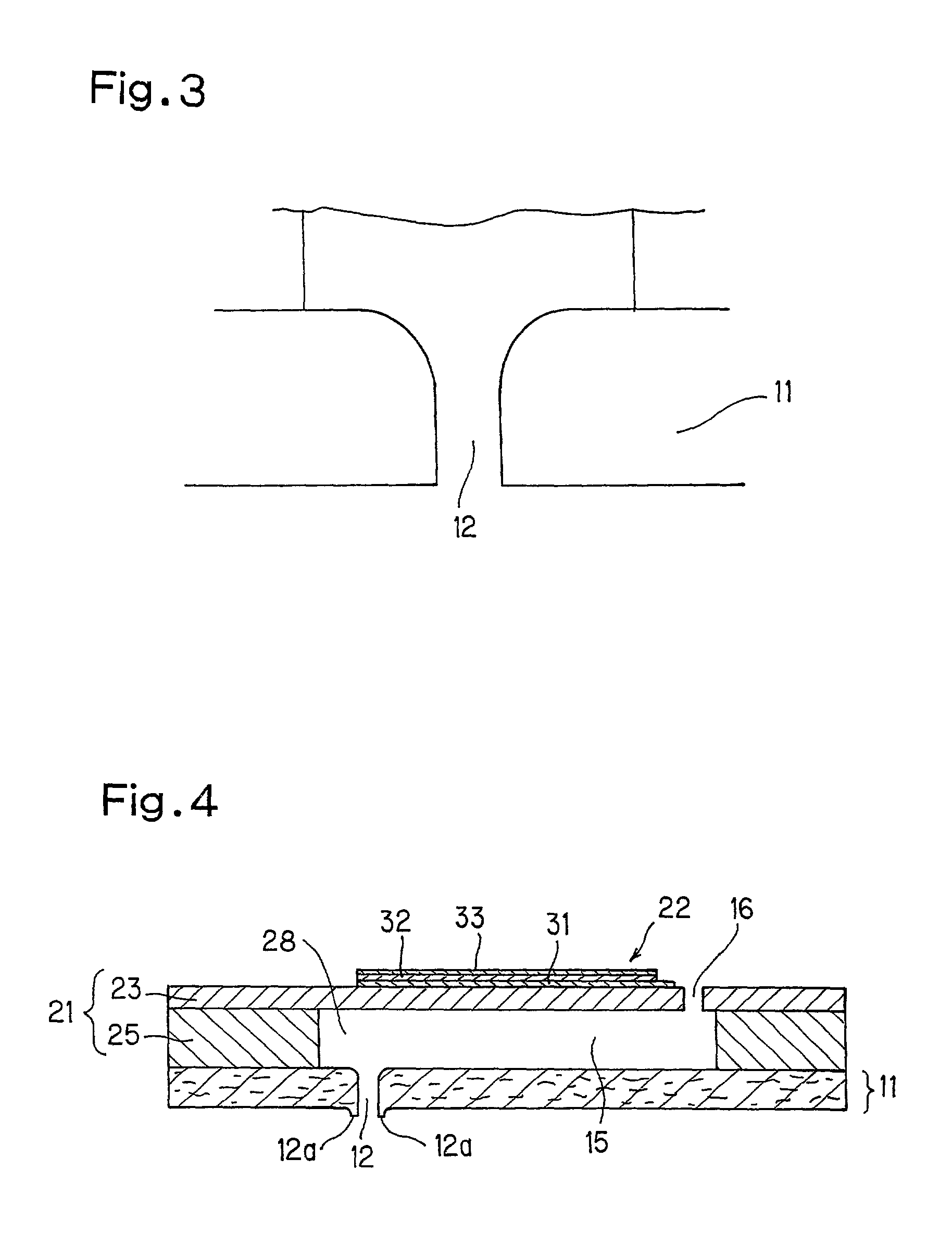
[0036] There was used a powder-producing device having a structure shown in FIG. 3 attached to the application of Japanese Patent Application 9-335210, on which a liquid injection device is mounted thereon shown in FIG. 4 of the present invention.

[0037] Ethyl alcohol solution of zirconium chloride is intermittently sprayed inside a quartz furnace 43 having an external heater 42 by an electromagnetic shutter 41 to give liquid drops. The liquid drops in the furnace 43 were dried and thermally decomposed to obtain a zirconia ceramic powder A.

[0038] The obtained zirconia ceramic powder A had an average particle diameter of 20 .mu.m and was so uniform that the particle-size distribution was within +10% of the average particle diameter.

[0039] After the powder was produced, conditions of adhesion of solid components in a tip part of the nozzle were observed, and no substantial adhesion of solid components was found.

[0040] Industrial Applicability

[0041] As described above, in a nozzle of th...


PUM

PropertyMeasurementUnit
aspect ratioaaaaaaaaaa
particle-size distributionaaaaaaaaaa

Abstract

A nozzle for a liquid injection device, wherein a ceramic green sheet (11) used as a bottom part of a liquid injection device having a nozzle (12) disposed between a die (2) and a stripper (3) storing a punch (4) and the punch (4) is moved to form a hole part constituting the nozzle (12), the green sheet (11) is disposed between a die (2') having a cavity wherein the outer shape of a projected part (12a) of the nozzle (12) is reversed and a stripper (3') storing a punch (5) so that it is positioned in the direction opposite to that in the previous disposition and the punch (5) is moved to obtain the outer shape of the nozzle (12), and the green sheet (11) is baked, whereby, even in a drying device to which air is constantly applied vertically to the delivery direction of liquid, no injected liquid is deposited substantially at the tip part of the nozzle (12).

Description

[0001] The present invention relates to a nozzle for a liquid injection device, a method for producing the nozzle, and a liquid injection device having the nozzle.[0002] There has been hitherto known a liquid injection device as a device for discharging liquid as fine particles. For example, such a device is disclosed in Japanese Patent Laid-Open No. 6-40030. However, in some cases, air is compulsorily sent to a portion around a liquid injection hole, i.e., a tip of a nozzle for the purpose of evaporation or drying of injected liquid, concentration of solid components contained in the liquid, promotion of momentary movement of the injected liquid, or the like. Since a tip part of the nozzle is formed to have the same height as an outer frame of a unitarily molded device as shown in FIG. 3 in each of these devices, liquid injected along the outer frame is prone to form a thin film due to its own surface tension.[0003] Once such a film is formed, the film acts mutually with liquid sub...

Claims


Application Information

Patent Timeline
Patent Type & Authority Applications(United States)
IPC IPC(8): B05B1/00B28B11/12B41J2/135
CPCB05B1/00B28B11/12Y10S239/19Y10T29/49433Y10T29/49432
Inventor TAKEUCHI, YUKIHISATSUJI, HIROYUKITAKAHASHI, NOBUO
Owner NGK INSULATORS LTD
Why Eureka
Try Eureka