Method for generating moisture, reactor for generating moisture, method for controlling temperature of reactor for generating moisture, and method for forming platinum-coated catalyst layer

a catalyst layer and catalyst technology, applied in the direction of physical/chemical process catalysts, chemical processes, other chemical processes, etc., can solve the problems of difficult control of the amount of generated water, easy thereby stopping combustion, and narrow control range of water to oxygen (moisture content/oxygen)

Inactive Publication Date: 2001-11-22
FUJIKIN INC +1
View PDF0 Cites 36 Cited by
  • Summary
  • Abstract
  • Description
  • Claims
  • Application Information

AI Technical Summary

Problems solved by technology

However, in the process of FIG. 52, there is a problem in that if the feed rate of hydrogen gas H.sub.2 or oxygen gas O.sub.2 is reduced to decrease the water amount, combustion can easily be thereby stopped and it is therefore extremely difficult to apply controls for decreasing the generated water amount, and a control range of a ratio of water to oxygen (moisture content / oxygen) is narrow.
The process has a difficulty in that because raw gas is fed directly into the reactor pipe, when combustion stops an interlock mechanism becomes indispensable to prevent explosion.
In addition, there is also a problem in that when gas flow rate is reduced, flames are generated in the vicinity of the nozzle, SiO.sub.2 composing the quartz nozzle evaporates, and these volatile materials mix in a reactor atmosphere (H.sub.2O+O.sub.2) and contaminate a gas (H.sub.2O.sub.+O.sub.2) fed to the semiconductor manufacturing equipment to such an extent that it can no longer be used for manufacturing high-performance semiconductors.
However, the water generating process using the equipment shown in FIG. 53 still has many problems that must be solved.
In particular, there is a case in which hydrogen or inert gas is added to water to adjust an oxidation-reduction power, and N.sub.2 O, etc. are added to water in order to improve interface characteristics of Si and SiO.sub.2, and in such event, an increase of the reactor size results in an increase of gas consumption rate, posing a serious problem from a standpoint of economy, etc.
It is also a problem that even if hydrogen and oxygen finish the reaction completely, the product gas is a mixture gas of moisture and argon, and it is unable to output high-purity water only or a mixture gas of water and oxygen.
A second problem is a problem of responsiveness and reactivity of water generation.
Because stainless pipes are used as a material having the catalytic action and catalytic action of pipe surfaces are utilized, it is unable to achieve a large reaction gas rate per unit surface area.
A third problem is safety.
When the temperature of the reaction pipe 54 is lowered, there is a problem in that the reaction gas increases.

Method used


Image

  • Method for generating moisture, reactor for generating moisture, method for controlling temperature of reactor for generating moisture, and method for forming platinum-coated catalyst layer
  • Method for generating moisture, reactor for generating moisture, method for controlling temperature of reactor for generating moisture, and method for forming platinum-coated catalyst layer
  • Method for generating moisture, reactor for generating moisture, method for controlling temperature of reactor for generating moisture, and method for forming platinum-coated catalyst layer

Examples


first embodiment

[0199] First Embodiment of Third and Fourth Reactors

[0200] Referring again to the drawings, a first embodiment of the third and fourth water-generating reactors according to this invention will be described.

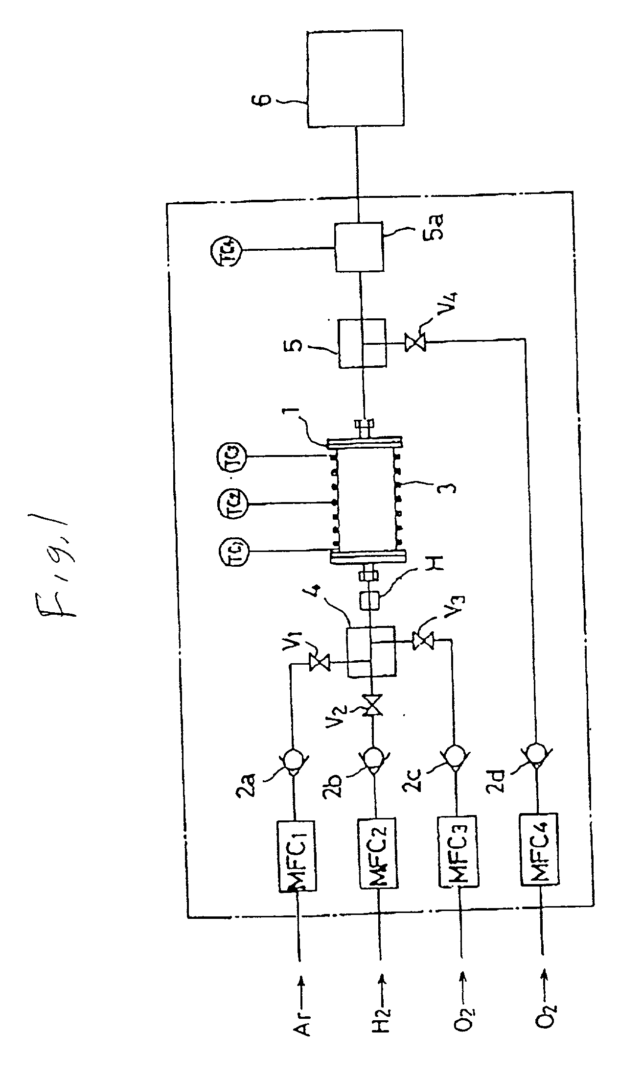
[0201] FIG. 38 and FIG. 39 show the first embodiment of the third and the fourth water-generating reactors, and correspond to a 11th embodiment reactor, overall. In FIGS. 38 and 39, numeral 10 designates a reactor, numeral 11a a reactor body, numerals 12, 13 reactor-body members (flanges), numeral 14 platinum coating film, numeral 15 an inlet for raw material gas, numeral 16 a water and moisture gas outlet, numeral 17 a gasket, numeral 18 a clamp, numeral 19 a heater, and numeral 20 thermocouples.

[0202] The reactor 10 comprises two reactor body members (flanges) 12, 13 installed opposite to each other via the gasket 17 and air-tightly tightened and fixed by the clamp 18 with a specified space maintained between them. The reactor body members (flanges) 12, 13 are made of stainless...

second embodiment

[0229] Second Embodiment

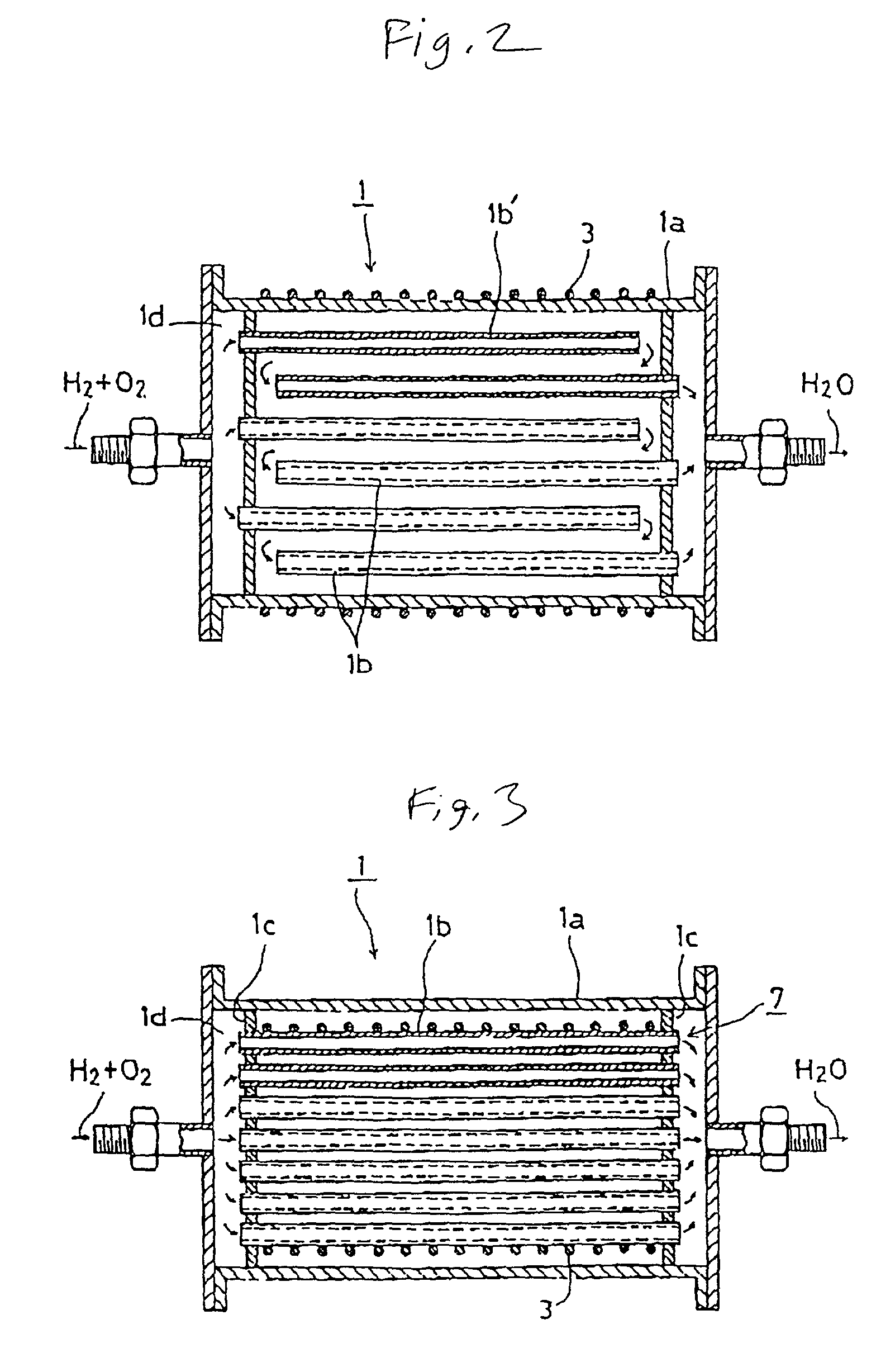
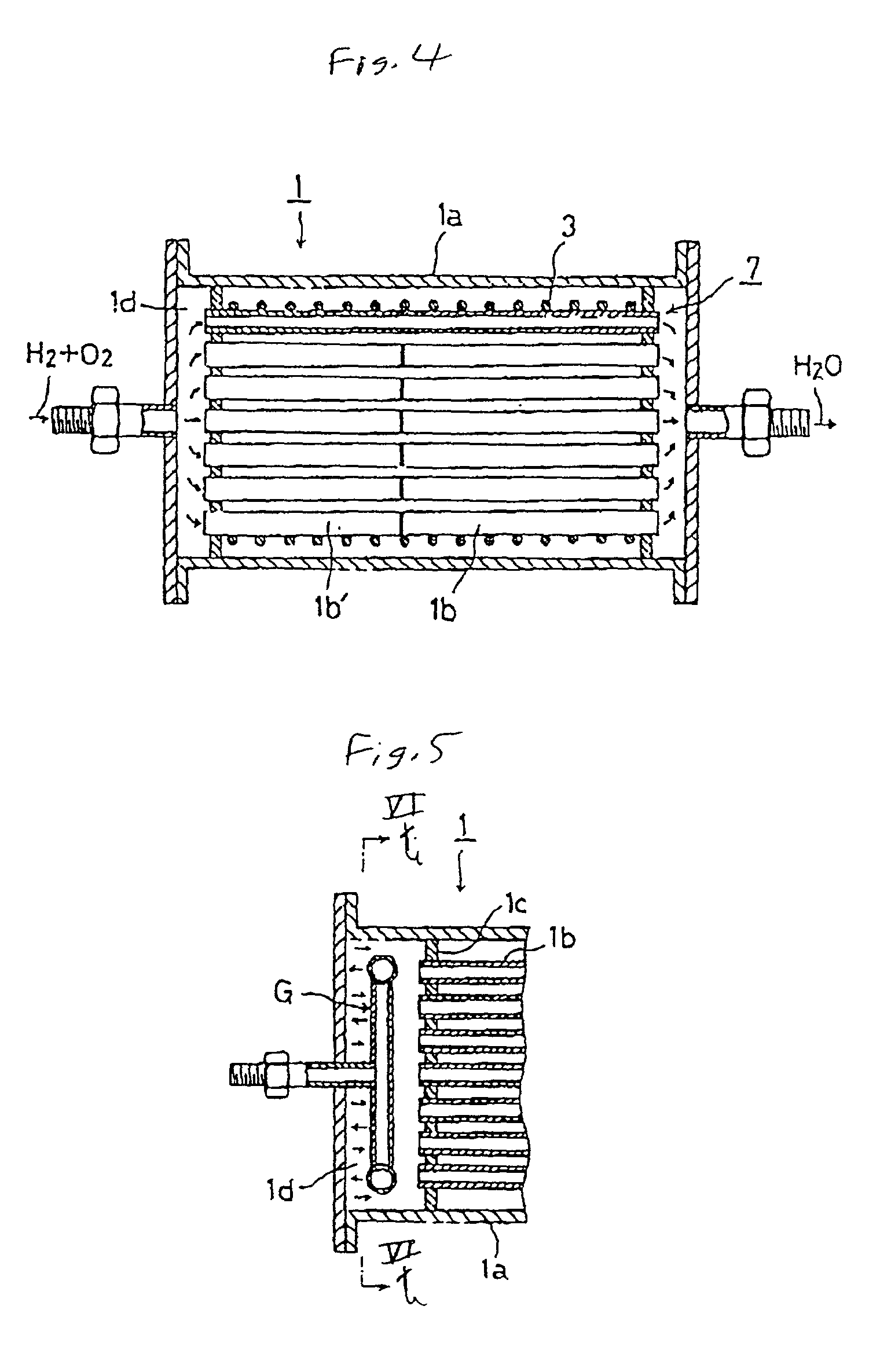
[0230] FIG. 43 shows a vertical cross-sectional view of a reactor related to a second embodiment of the third and the fourth water-generating reactors according to this invention, and corresponds to a 12th overall embodiment of a reactor of this invention. In FIG. 43, a reactor 21 is formed to have a short cylindrical form, and at the same time, a diffusing member 28 for diffusing a mixture gas is placed inside, thereby bringing gas in uniform contact with a platinum coating film 32, and with this configuration, localized temperature rises of the platinum coating film 32 and the base carrier member is designed to be prevented.

[0231] That is, in FIG. 43, numerals 21 designates the reactor, 22, 23 reactor body members, 24 a gas supply joint, 25 a water and moisture gas take-out joint, 26 a filter flange, 27 a reactor fixing bolt, 28 a gas diffusion member, 29a, 29a' reflector plates, 30 a filter, 31 a filter retainer, and 32 the platinum coating film. The react...


PUM

PropertyMeasurementUnit
temperatureaaaaaaaaaa
thickaaaaaaaaaa

Abstract

A reactor comprising a body made of a heat-resistant material and having an inlet and an outlet for water / moisture gas, having a gas-diffusing member provided in an internal space of the body, and having a platinum coating on an internal wall surface of the body. Hydrogen and oxygen fed from the inlet are diffused by the gas-diffusing member and then come into contact with the platinum coating to enhance reactivity, thereby producing water. A temperature of the reactor is held to be below an ignition temperature of hydrogen or a hydrogen-containing gas. The platinum-coated catalyst layer on the internal wall of the reactor body is formed by treating the surface of the internal wall of the body, cleaning the treated surface, forming a barrier coating of a nonmetallic material of an oxide or nitride on the wall surface, and forming the platinum coating on the barrier coating.

Description

[0001] The present invention is primarily used in semiconductor manufacturing facilities. More specifically, the present invention is used for supplying water when silicon dioxide film is affixed by a so-called water oxidation method (or steam oxidation method) using a process chamber.DESCRIPTION OF THE PRIOR ART[0002] For example, for affixing a silicon oxide film by the water oxidation method in semiconductor manufacture, high-purity water is required.[0003] Consequently, for a conventional affixing of a silicon oxide film, as shown in FIG. 52, a process in which hydrogen gas H.sub.2 and oxygen gas O.sub.2 are allowed to combust in a quartz furnace 50 has been extensively used in which water generated by the combustion of these two gases is fed into semiconductor manufacturing equipment; and the oxide film is formed on the Si wafer surface.[0004] In FIG. 52, numeral 51 designates a hydrogen gas nozzle, 52 a Si chip for ignition held in a vicinity of a top side of the hydrogen gas ...

Claims


Application Information

Patent Timeline
Patent Type & Authority Applications(United States)
IPC IPC(8): C01B5/00
CPCC01B5/00
Inventor OHMIKAWADA, KOJITANABE, TOSHIKAZUNITTA, TAKAHISAIKEDA, NOBUKAZUMORIMOTO, AKIHIROHIRAO, KEIJIMOROKOSHI, HIROSHIMINAMI, YUKIO
Owner FUJIKIN INC
Why Eureka
Try Eureka