Devices and methods for interconnecting vessels

a technology of interconnection and vessels, applied in the field of anastomosis and anastomosis devices, can solve the problems of poor anastomosis patency, damage to the vessel wall, and difficulties and problems that have been presented

Inactive Publication Date: 2001-11-22
DATASCOPE
View PDF0 Cites 71 Cited by
  • Summary
  • Abstract
  • Description
  • Claims
  • Application Information

AI Technical Summary

Problems solved by technology

Surgeons must delicately sew the vessels together being careful not to suture too tightly so as to tear the delicate tissue, thereby injuring the vessel which may then result in poor patency of the anastomosis.
Recently, some surgeons have used staples and associated stapling mechanisms and techniques to form an anastomosis, but many of the same difficulties and problems have presented themselves.
Basically, the tension and/or compression forces exerted on the vessel walls as a result of suturing and stapling can result in damage to the vessel wall, even to the extent of causing tissue necrosis.
Damage to the intima of a vessel is particularly problematic as it may inhibit the natural bonding process that occurs between the anastomized vessels and which is necessary for sufficient patency.
Futhermore, damaged vessel walls are likely to have protuberances that when exposed to the bloodstream could obstruct blood flow or may produce turbulence which can lead to formation of thrombus, stenosis and possible occlusion of the artery.
The procedures are made more difficult due to the multiple characteristics that are unique to each anastomosis and to each patient.
For example, the arteries' internal diameter dimensions are difficult to predict and the inside walls are often covered with deposits of stenotic plaque which creates the risk of dislodging plaque into the patient's blood stream during the anastomosis procedure.
The resulting emboli in turn create a greater risk of stroke for the patient.
The vessel walls can also be friable and easy to tear, and are often covered with layers of fat and/or are deeply seated in the myocardium, adding to the difficulty of effectively and safely performing conventional anastomotic procedures.
Cardiac surgeons sometimes inadvertently suture too loosely, resulting in leakage of fluid from the anastomosis.
In addition to creating a surgical field in which it is difficult to see, leakage of fluid from the anastomosis can cause serious drops in blood pressure, acute or chronic.
The loss of blood may cause other deleterious effects on the patient's hemodynamics that may even enda...

Method used


Image

  • Devices and methods for interconnecting vessels
  • Devices and methods for interconnecting vessels
  • Devices and methods for interconnecting vessels

Examples


embodiment 12

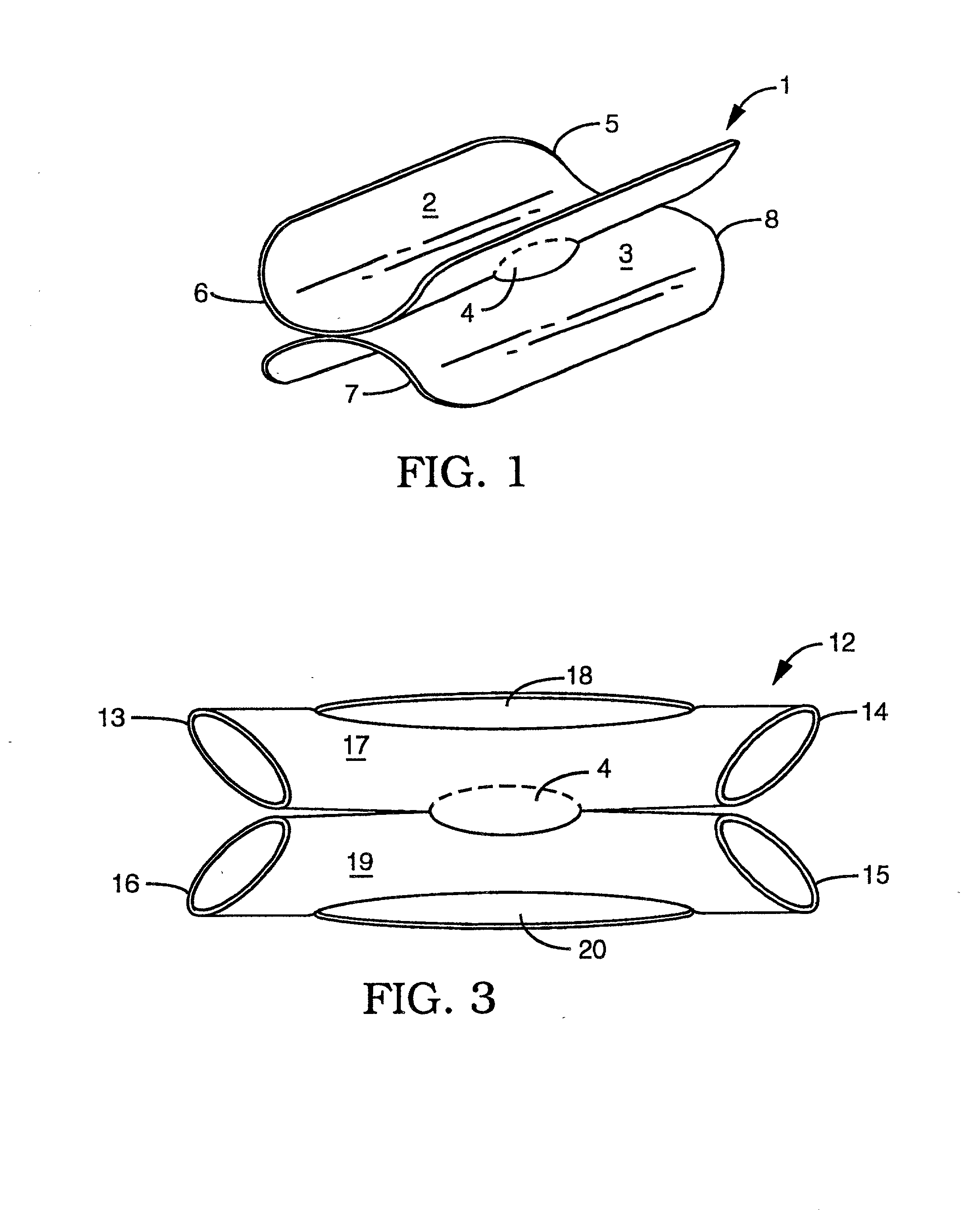
[0101] FIG. 3 shows an alternative embodiment 12 of the invented device having tubular segments 17 and 19. Tubular segment 17 comprises tapered ends 13 and 14 and tubular segment 19 comprises tapered ends 15 and 16. The tapering of these ends may have a low friction coating and be very smooth thereby providing a number of advantages which include making it easier to insert into a vessel. The configuration of FIG. 1 shows that the first segment and second segment are each configured in the form of a portion of a cylinder in an unconstricted state. However, the device could be configured so that each segment is a complete cylinder (see FIG. 3) in an unconstricted or constricted state. An advantage of having each of the segments a partial cylinder is the ability to conform to a wider range of different vessel diameters to improve the fitting range. Another advantage is the maximizing of the amount of endothelial wall of the vessel not covered by the device 12 to minimize any negative b...

experimental examples

[0162] An experiment was conducted to test the ease of insertion, sealing properties and retention ability of the segments / flanges of the anastomotic devices of the present invention. Various embodiments of the segments / flanges were implanted into a vessel of a swine weighing 39.2 kg. Vessel having diameters of 2, 3 and 4 mm were used as implant vessels due to their similiarity in size to average human coronary arteries. Seven segments were used, all made of a silicone-urethane copolymer (Polymer Technology Group, Pursil 80A) and having a semi-ellipsoidal shape with short and long axis dimensions of 9 by 15 mm. The segments had varying thicknesses ranging from 100 to 380 microns (100.times.10.sup.-3 to 380.times.10.sup.-3 mm). Prior to implant, a suture was secured to the center of each segment to aid in testing the stability and the ability of the segments to keep from dislodging from the arteriotomy. The swine was placed under general anesthesia and, once adequately sedated, a pre...


PUM


Abstract

The present invention provides implantable devices and associated methods for interconnecting human vessels in a side-to-side or an end-to-side arrangement rapidly, safely and in a minimally invasive manner. The devices comprises at least a first segment, a second component, and a flow opening between the at least one segment and the second component when operatively used. The first segment is flexible and has physical and mechanical properties which allow it to be easily inserted into a vessel, to conformably seal with the inside wall of the vessel and to be resistant to dislodging from the vessel. The second component may comprise a second segment having the same or a similar configuration as the first segment or may be a tubular member which extends from the first segment. The first and second segments are flexible for easy insertion into an incision made within the side of each vessel. Upon release from a constricted state, each flexible segment subsequently conforms to the interior walls of a vessel to provide a sealing contact along the contact surface of the segment inserted within. The tubular member is configured to be inserted into a transected end of a vessel. The flow opening provides fluid interconnectivity between the vessels connected by the implanted devices. The devices are configured so as to: (1) not impede flow inside a vessel; (2) prevent leakage from the incisions within the vessels; and (3) apposition the vessels toward each other allowing the vessels to heal together so that flow in one vessel may flow to the other.

Description

[0001] This application is a continuation-in-part of application serial no. PCT / US00 / 20588 filed on Jul. 28, 2000; which application is a continuation-in-part of application Ser. No. 09 / 363,309 filed on Jul. 28, 1999 and application Ser. No. 09 / 363,310 filed on Jul. 28, 1999, now U.S. Pat. No. 6,165,185 issued on Dec. 26, 2000; the disclosures of which are herein incorporated by reference.[0002] 1. Technical Field[0003] The field of this invention is anastomosis and anastomotic devices.[0004] 2. Background of the Invention[0005] The human body has numerous vessels carrying fluid to essential tissues and areas for recirculation or excretion. When vessels become damaged, severed or wholly occluded due to physiological problems, certain sections must be bypassed to allow for the free and continuous flow of fluids. Anastomosis is performed for the purpose of connecting different conduits together to optimize or redirect flow. In cardiac surgery, anastomosis is done to bypass the occlude...

Claims


Application Information

Patent Timeline
IPC IPC(8): A61B17/00A61B17/04A61B17/11A61F2/06
CPCA61B17/11A61B2017/00867A61B2017/1107A61B2017/1135A61B2017/1139A61F2/064
Inventor AKIN, JODISALAHIEH, AMRMACK, MICHAELSHENNIB, HANIDEMOND, JACKSONYAMAMOTO, RONALD K.CONSTON, STANLEY R.
Owner DATASCOPE
Why Eureka
Try Eureka