Micro integrated global positioning system/inertial measurement unit system

a global positioning system and integrated technology, applied in wave based measurement systems, navigation instruments, instruments, etc., can solve the problems of drift in output (position, velocity, attitude, etc.), inability to directly obtain the position rate measurement from the platform, and complex gimbaled inertial navigation systems. achieve the effect of high accuracy, position, velocity, attitude and heading measuremen

Inactive Publication Date: 2002-01-24
AMERICAN GNC
View PDF0 Cites 181 Cited by
  • Summary
  • Abstract
  • Description
  • Claims
  • Application Information

AI Technical Summary

Benefits of technology

0046] A main objective of the present invention is to provide a micro integrated GPS / IMU system, which can produce highly accurate, position, velocity, attitude, and heading measurements of the carrier under dynamic environments.

Problems solved by technology

But attitude rate measurements can not be directly obtained from the platform.
But, a gimbaled inertial navigation system is more complex and expensive than a strapdown inertial navigation system.
However, an inertial navigation system is expensive and is degraded with drift in output (position, velocity, and attitude) over an extended period of time.
It means that the position errors, velocity errors, and attitude errors increase with time.
This error propagation characteristic is primarily caused by many error sources, such as, gyro drift, accelerometer bias, misalignment, gravity disturbance, initial position and velocity errors, and scale factor errors.
However, current highly accurate inertial sensors are very expensive with big size and heavy weight.
However, the GPS signals may be intentionally or unintentionally jammed or spoofed, and the GPS receiver antenna may be obscured during carrier attitude maneuvering, and the performance degrades when the signal-to-noise ratio of the GPS signal is low and the carrier is undergoing highly dynamic maneuvers.
However, this attitude measurement system retains the characterization of low bandwidth and is susceptible to shading and jamming, and requires at least 3 antennas configurations for a three-axis attitude solution, and requires antenna separation enough for high attitude resolution.
Because of the inherent drawbacks of a stand-alone inertial navigation system and a stand-alone GPS receiver, a stand-alone inertial navigation system or a stand-alone GPS receiver can not meet mission requirements under some constraints, such as low cost, long-term high accuracy, high rate output, interrupt-free, etc.
This navigation capability is unattainable in either one of the two systems alone.
(2) An inertial navigation system not only provides navigation information when the GPS signal is lost temporarily, but also reduces the search time required to reacquire GPS signals.
(iii) High power consumption,
(iv) Limited lifetime, and Long turn-on time.
(iii) High power consumption,
(iv) Limited lifetime, and Long turn-on time.
These present deficiencies of conventional integrated GPS / IMU systems prohibit them from being used in the emerging cost-sensitive commercial applications, such as control of phased array antennas for mobile communications, automotive navigation, and handheld equipment.
MEMS inertial sensors offer tremendous cost, size, and reliability improvements for guidance, navigation, and control systems, compared with conventional inertial sensors.
Although the MEMS angular rate sensors and MEMS accelerometers and GPS chipsets are available commercially and have achieved micro chip-size and low power consumption, they are not yet technically equipped to construct a high performance, small size, and low power consumption integrated GPS / IMU systems based on the conventional technologies.

Method used


Image

  • Micro integrated global positioning system/inertial measurement unit system
  • Micro integrated global positioning system/inertial measurement unit system
  • Micro integrated global positioning system/inertial measurement unit system

Examples


Embodiment Construction

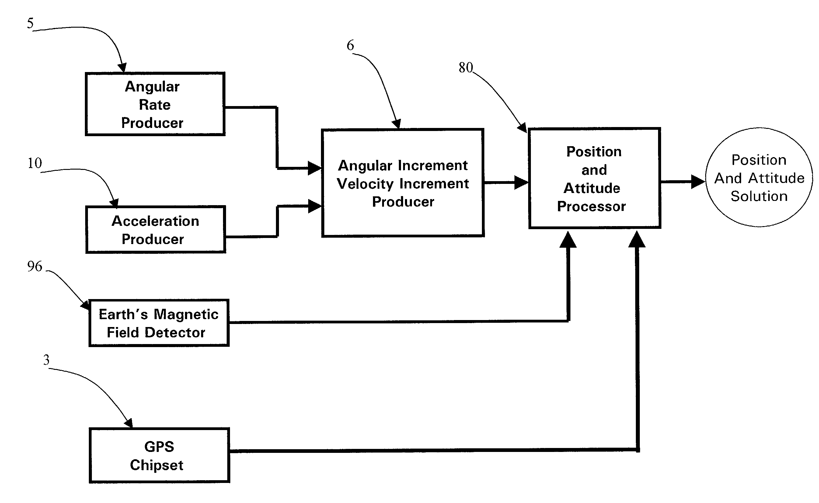
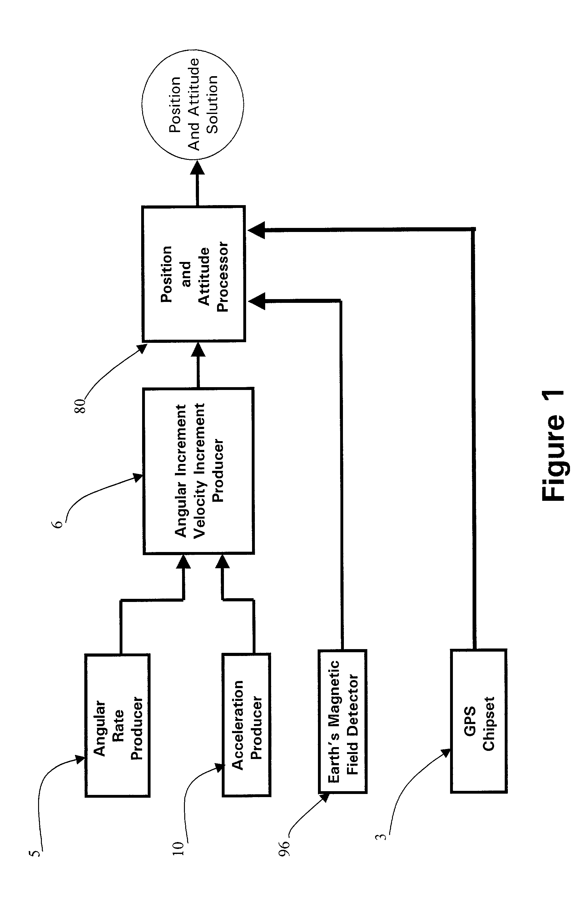
[0086] The present invention provides a micro integrated GPS / IMU system to blend raw motion measurements from the micro inertial measurement unit and a GPS chipset to improve the accuracy of the position, velocity, and attitude solution deduced from raw motion measurements for the micro inertial measurement unit only, in order to output highly accurate GPS / IMU mixed navigation solution.

[0087] Referring to FIG. 1, the micro integrated GPS / IMU system of a carrier, which comprises a body frame, comprises:

[0088] an angular rate producer 5, producing orthogonal three-axis (X axis, Y axis and Z axis) electrical angular rate signals;

[0089] an acceleration producer 10, producing orthogonal three-axis (X-axis, Y axis and Z axis) electrical acceleration signals;

[0090] an angular increment and velocity increment producer 6, converting the three-axis electrical angular rate signals into digital angular increments and for converting the three-axis electrical acceleration signals into digital vel...


PUM


Abstract

A micro integrated Global Positioning System (GPS)/Inertial Measurement Unit (IMU) System, which is adapted to apply to output signals proportional to rotation and translational motion of a carrier and GPS measurements of the carrier, respectively from angular rate sensors, acceleration sensors, and GPS chipset, is employed with MEMS angular rate and acceleration sensors and GPS chipset. Compared with a conventional IMU/GPS system, the system of the present invention uses an integrated processing scheme by means of digital closed loop control of the dither driver signals for MEMS angular rate sensors, a feedforward open-loop signal processing scheme of the IMU, digital temperature control and compensation, the earth's magnetic field-based heading damping, robust error estimator, and compact sensor and circuit architecture and dramatically shrinks the size of mechanical and electronic hardware and power consumption, meanwhile, obtains highly accurate motion measurements.

Description

CROSS REFERENCE OF RELATED APPLICATIONS[0001] This is a regular application of a provisional application having an application number of No. 60 / 219,957 and a filing date of Jul. 20, 2000.BACKGROUND OF THE PRESENT INVENTION[0002] 1. Field of the Present Invention[0003] The present invention relates to a motion measurement system, and more particularly to an integrated Global Positioning System (GPS) / Inertial Measurement Unit (IMU) System in micro size, which can produce highly accurate, digital angular rate, acceleration, position, velocity, and attitude measurements of a carrier under dynamic environments.[0004] 2. Description of the Related Arts[0005] In the past decade, an IMU or GPS receiver is commonly employed to determine the motion measurement of a carrier.[0006] The IMU is a key part of an inertial navigation system (INS). Generally, an INS consists of an IMU, a microprocessor and associated embedded navigation software. The components of the IMU include the inertial sensors...

Claims


Application Information

Patent Timeline
Patent Type & Authority Applications(United States)
IPC IPC(8): G01C21/16G01S5/14G01S19/47
CPCG01C21/165G01S19/35G01S19/41G01S19/47G01S19/52G01S19/53G01C21/1654
Inventor MCCALL, HIRAMLIN, CHING-FANG
Owner AMERICAN GNC
Why Eureka
Try Eureka