Fluid drilling system with drill string and retro jets

a drilling system and jet technology, applied in the direction of directional drilling, survey, borehole/well accessories, etc., can solve the problems of coiled tubing, complicated and expensive ways to advance it into the borehole, and the cost of coiled tubing is significant and the cost of coiled tubing is high, so as to reduce the incident

Inactive Publication Date: 2002-01-31
THE UNIV OF QUEENSLAND
View PDF0 Cites 32 Cited by
  • Summary
  • Abstract
  • Description
  • Claims
  • Application Information

AI Technical Summary

Benefits of technology

[0033] A major advantage of using a high pressure flexible hose as the drill string is that it can be fed and retracted continuously from a drum. This eliminates the requirement to continuously add and take off rigid drill rods. Significant productivity gains are therefore possible with this technology. Although coiled steel tubing which is known technology can be used in a similar way, the capital cost of the tubing and winches are considerably greater than for this invention.
[0047] The cutting apparatus can be steered by a steering means. One form of the steering means comprises fluid passing through the retro jet nozzles which can be selectively deflected by a deflecting assembly. The deflecting assembly can thereby assist in steering the cutting apparatus. The deflecting assembly may comprise a deflecting member which can be moved selectively into and out of the fluid jet stream to deflect the stream. Suitably, the deflecting member comprises a protrusion, or like member on a ring, the ring extending about the retro sub member. Rotation of the ring can cause the deflecting member to selectively pass into and out of a fluid jet stream. The ring may be rotated by an actuator which may be located within the cutting apparatus.

Problems solved by technology

Additionally complicated and expensive ways are required to advance it in to the borehole.
The only other known technology capable of achieving this is again coiled tubing which has a significant greater capital cost associated with it as mentioned earlier.
Additionally coiled tubing can only be made to turn through an ultra-short-radius by forcing the steel tubing past the elastic limit of the material.
The strains involved seriously reduces the working life of the tubing which typically means that the section of tubing that passes through the ultra-short-radius is not retracted and complicated methods have to be used to sever it, including mechanical and electro chemical shearing devices.
This adds significantly to costs.
A further disadvantage of coiled tubing for directional drilling in coal is that if not retracted, the tubing can represent a safety hazard for the subsequent mining of the coal by underground methods.
The chemicals used to sever the tubing may also adversely affect the permeability of the coal seam.

Method used


Image

  • Fluid drilling system with drill string and retro jets
  • Fluid drilling system with drill string and retro jets
  • Fluid drilling system with drill string and retro jets

Examples


Embodiment Construction

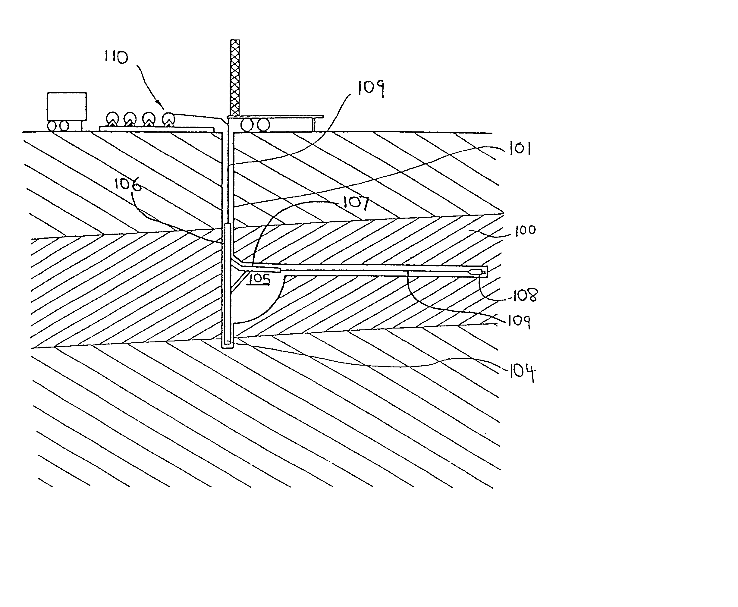
[0063] Referring to the drawings and initially to FIG. 9, there is shown diagrammatically a system for cutting a substantially horizontal passage into a coal seam 100. FIG. 9 shows a vertical bore 101 extending through the coal seam. A whipstock apparatus 104 is positioned in the bore and in a pre-formed cavity 105. The whipstock apparatus can be that described in the applicants co-pending international patent application, the contents of which are incorporated herein by suitable cross reference. Whipstock apparatus 104 has a main body 106 sized to allow the whipstock to be inserted into the bore. An extendible arm 107 is attached to the main body portion, and the arm can be hydraulically erected to adopt a horizontal orientation (other angles are also possible).

[0064] The fluid drilling apparatus 108 which is the subject of the current application can be housed in the arm 107, such that when the arm is erected, the apparatus can start cutting a bore in the coal seam. The flexible h...


PUM

PropertyMeasurementUnit
lengthaaaaaaaaaa
internal pressuresaaaaaaaaaa
radiusaaaaaaaaaa

Abstract

A self-advancing drilling system comprising a drilling apparatus, the drilling apparatus, the drilling apparatus having at least one leading fluid cutting nozzle, means on the drilling apparatus to provide forward movement to the drilling apparatus, the drilling system further comprising a drill string formed from recoverable flexible hose.

Description

[0001] This invention relates to a fluid drilling system and particularly relates to a self-advancing fluid drilling system which can be used in a variety of mining applications, including but not limited to, drilling into coal seams, to drain methane gas.[0002] Fluid drilling systems are known and use water under high pressure to cut solids such as soft rock, coal and the like. These water jet drilling systems are finding greater acceptance in the mining industry and can be used instead of the traditional mechanical cutting heads.[0003] The known water jet drilling systems all have a cutting apparatus advanced by forces transmitted along a rigid drill string or in one instance by fluid pressure exerted on a piston type arrangement. The cutting apparatus has one or more water jet cutting nozzles on a leading portion of the apparatus.[0004] Conventionally, in order to cut a circular hole, the rigid drill string is rotated thereby sweeping the forward cutting jets through a circular p...

Claims


Application Information

Patent Timeline
Patent Type & Authority Applications(United States)
IPC IPC(8): E21B4/18E21B7/06E21B7/08E21B7/18E21B10/60E21B10/61E21B17/20E21B21/00E21B41/00E21B43/26E21B43/29E21B43/32E21F7/00G01N33/50G01N33/68
CPCE21B4/18E21B7/061E21B7/065E21B7/18E21B10/61E21B17/20E21B21/00E21B41/0078E21B43/26E21B43/292G01N33/5091G01N33/6863G01N33/6869
Inventor TRUEMAN, ROBERTMEYER, TIMOTHY GREGORY HAMILTONSTOCKWELL, MATTHEW
Owner THE UNIV OF QUEENSLAND
Why Eureka
Try Eureka