
Battery, lead memver for battery connection, and battery pack using the same

a lead memver and battery connection technology, applied in the direction of cell components, cell components, jackets/case materials, etc., can solve the problems of complicated irregular surfaces, two members are not uniformly in contact with each other, and the difficulty of increasing the strength of weld between the battery container and the lead member

Inactive Publication Date: 2002-01-31
TOSHIBA BATTERY
View PDF0 Cites 16 Cited by
  • Summary
  • Abstract
  • Description
  • Claims
  • Application Information

AI Technical Summary

Benefits of technology

[0027] An object of the present invention is to provide a battery and a lead member, designed so that high strength of weld between a battery container and the lead member can be maintained with less variation despite lower current supply thereto when the lead member is welded to the outer surface of the battery container by the parallel resistance welding method.
[0028] Another object of the invention is to provide a battery and a lead member, which require no high current supply for welding, so that welding electrodes cannot be easily fused to the lead member, and smooth welding processes can be composed without entailing production of melt dust.
[0029] Still another object of the invention is to provide a high-reliability battery pack that cannot be easily broken by external force such as impact.

Problems solved by technology

Microscopically, however, they are complicated irregular surfaces.
When the lead member is put on the surface of the battery container, therefore, these two members are not uniformly in contact with each other.
In the case where the battery container and the lead member are formed of a Ni-plated steel sheet, the following problems are believed to arise if they are welded by the parallel resistance welding method.
Increasing the strength of weld between the battery container and the lead member is pretty difficult and the range of operating conditions therefor is narrow.
If the weld strength is not very high, then welded joints on a battery pack that is incorporated in an electric or electronic device to be actually used will possibly be broken by impact to ruin the function of the device in case the device is dropped, for example.
If the weld strength varies, moreover, it can be supposed to lower the reliability of welding of welded structures of manufactured batteries and lead members, in consideration of the fact that the welding operation is usually continuously performed in a production line.
If this is done, however, the welding electrodes sometimes may be fused to the surface of the lead member, thereby preventing composition of smooth welding processes.
In some cases, furthermore, generation of excessive heat may results in production of melt dust of the metal material that constitutes the surface of the battery container and the lead member, thus lowering the weld strength, on the contrary.

Method used


Image

  • Battery, lead memver for battery connection, and battery pack using the same
  • Battery, lead memver for battery connection, and battery pack using the same
  • Battery, lead memver for battery connection, and battery pack using the same

Examples


examples 7 to 11

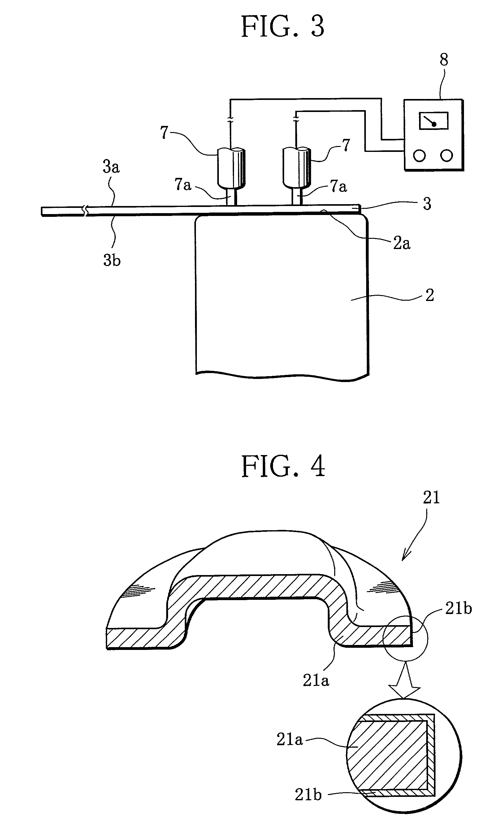
[0090] Layers of an Ni--Fe alloy with the thicknesses shown in Table 2 were formed on battery containers for varied plating times with use of a plating bath that is adjusted in composition so that the Fe contents of the layers were 20% by atomic percentage. Then, 30 batteries were assembled using the individual battery containers, and the aforesaid lead member (formed of a Ni-plated steel sheet) was put on the bottom surface of each battery container. The lead member and the battery container were subjected to resistance welding in a manner such that they are supplied with a welding current of 1.5 kA under a pressure loading of 22 N from the welding electrodes.

[0091] The value of this pressure loading is the sum of forces applied to the two welded electrodes. The forces applied individually to the electrodes are set at substantially equal values.

[0092] The weld strength was measured in the same manner as in the cases of Examples 1 to 6. Table 2 shows the maximum and minimum values o...

example 13

[0101] Battery cans and covers for AA-size batteries were prepared. A soft steel sheet was used as the material of any of these members.

[0102] A plating bath for an Ni--Co alloy was prepared containing 250 g / L of nickel chloride, 15 g / L of cobalt chloride, and 15 g / L of boric acid.

[0103] The battery cans and covers were electroplated in this plating bath under conditions including a pH of 3, current density of 1.5 A / dm.sup.2, and bath temperature of 20.degree. C., whereupon an Ni-15% Co alloy layer of 3-.mu.m thickness was formed on each of the respective surfaces of the battery cans and covers.

[0104] Thirty AA-size nickel-metal-hydride secondary batteries were assembled with use of these battery cans and covers. A lead member, formed of an Ni-plated soft steel sheet with 0.15 mm thick and 5 mm wide, was put on the bottom surface of each battery, and was subjected to resistance welding under the same conditions as in Examples 1 to 6.

[0105] Then, the weld strength was measured in the...

example 14

[0108] A plating bath was prepared containing 220 g / L of nickel sulfate, 30 g / L of nickel chloride, 40 g / L of nickel formate, 4.8 g / L of cobalt sulfate, 0.8 g / L of ammonium sulfate, 2 g / L of formaldehyde, and 28 g / L of boric acid.

[0109] The battery cans and covers used in Example 13 were electroplated in this plating bath under conditions including a pH of 3.7, current density of 5 A / dm.sup.2, and bath temperature of 65.degree. C., whereupon an Ni-7% Co alloy layer of 3-.mu.m thickness was formed on each of the respective surfaces of the battery cans and covers.

[0110] Twenty AA-size nickel-metal-hydride secondary batteries were assembled with use of these battery cans and covers. A lead member, formed of an Ni-plated soft steel sheet 0.15 mm thick and 5 mm wide, was put on the bottom surface of each battery, and was subjected to resistance welding under the same conditions as in Examples 1 to 6.

[0111] Then, the weld strength was measured in the same manner as in the cases of Example...


PUM

PropertyMeasurementUnit
thicknessaaaaaaaaaa
thicknessaaaaaaaaaa
thicknessaaaaaaaaaa

Abstract

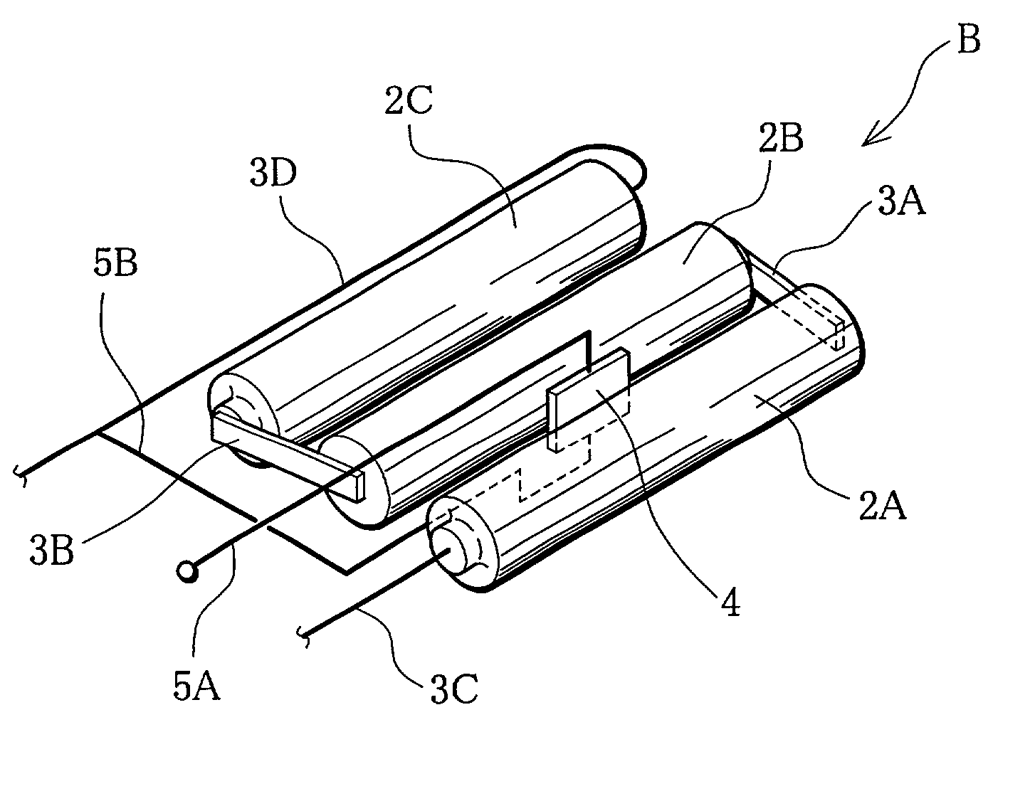
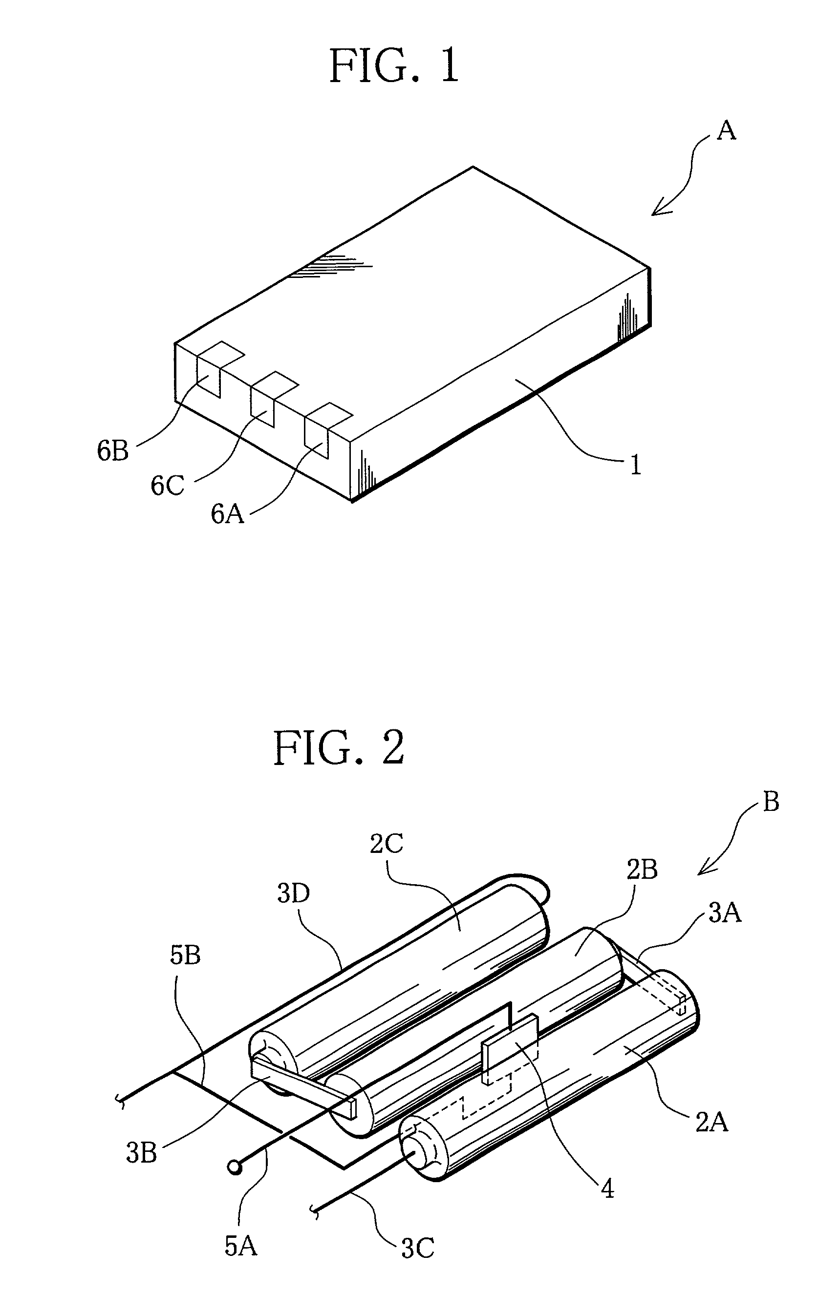
Provided are a battery and a lead member, designed so that high strength of weld between them can be maintained with less variation despite the supply of lower welding current thereto when the lead member is welded to the outer surface of the battery by the parallel resistance welding method, and a battery pack using the same. A layer of an Ni-based alloy, e.g., an Ni-Fe alloy, is formed on a part or the whole of the outer surface of the battery. The lead member for battery connection is composed of a substrate and an Ni-Sn alloy layer formed on that surface of the substrate which is welded to the outer surface of the battery. The battery pack is composed of a battery group that is assembled by using the battery and / or the lead member and stored in a shell.

Description

[0001] 1. Field of the Invention[0002] The present invention relates to a battery, a lead member for battery connection (hereinafter referred to as lead member) welded to the outer surface of the battery by the parallel resistance welding method, and a battery pack using the same, and more specifically, to a battery and a lead member having surface conditions such that high weld strength can be realized in a stable state between the lead member and a battery container of the battery when the lead member is welded to the outer surface of the battery, and a battery pack using the same.[0003] 2. Prior Art[0004] With the spread of various electric and electronic devices, an increasing number of devices have started to be designed so that they directly incorporate a battery pack that includes a plurality of connected batteries as drive sources. Charging or discharging the batteries of these devices requires use of lead members for electrical connection between the batteries and between p...

Claims


Application Information

Patent Timeline
Patent Type & Authority Applications(United States)
IPC IPC(8): C23C30/00H01M50/119H01M50/124H01M50/133H01M50/503H01M50/528
CPCC23C30/00H01M2/027H01M2/0275H01M2/204H01M2/22Y02E60/10H01M50/545H01M50/528H01M50/133H01M50/124H01M50/503H01M50/119
Inventor TSUKADA, MASAZUMINISHIKAWA, REJIKITAZUME, HIDEAKIMATSUI, TSUTOMUSHIMIZU, NORIYUKITANAKA, KAYOHOSOBUCHI, KAORU
Owner TOSHIBA BATTERY
Learn More