

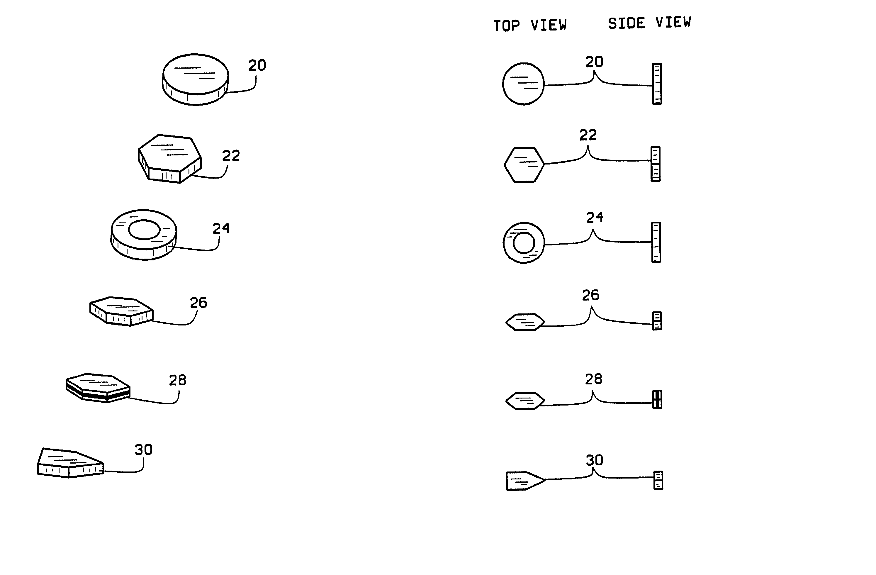
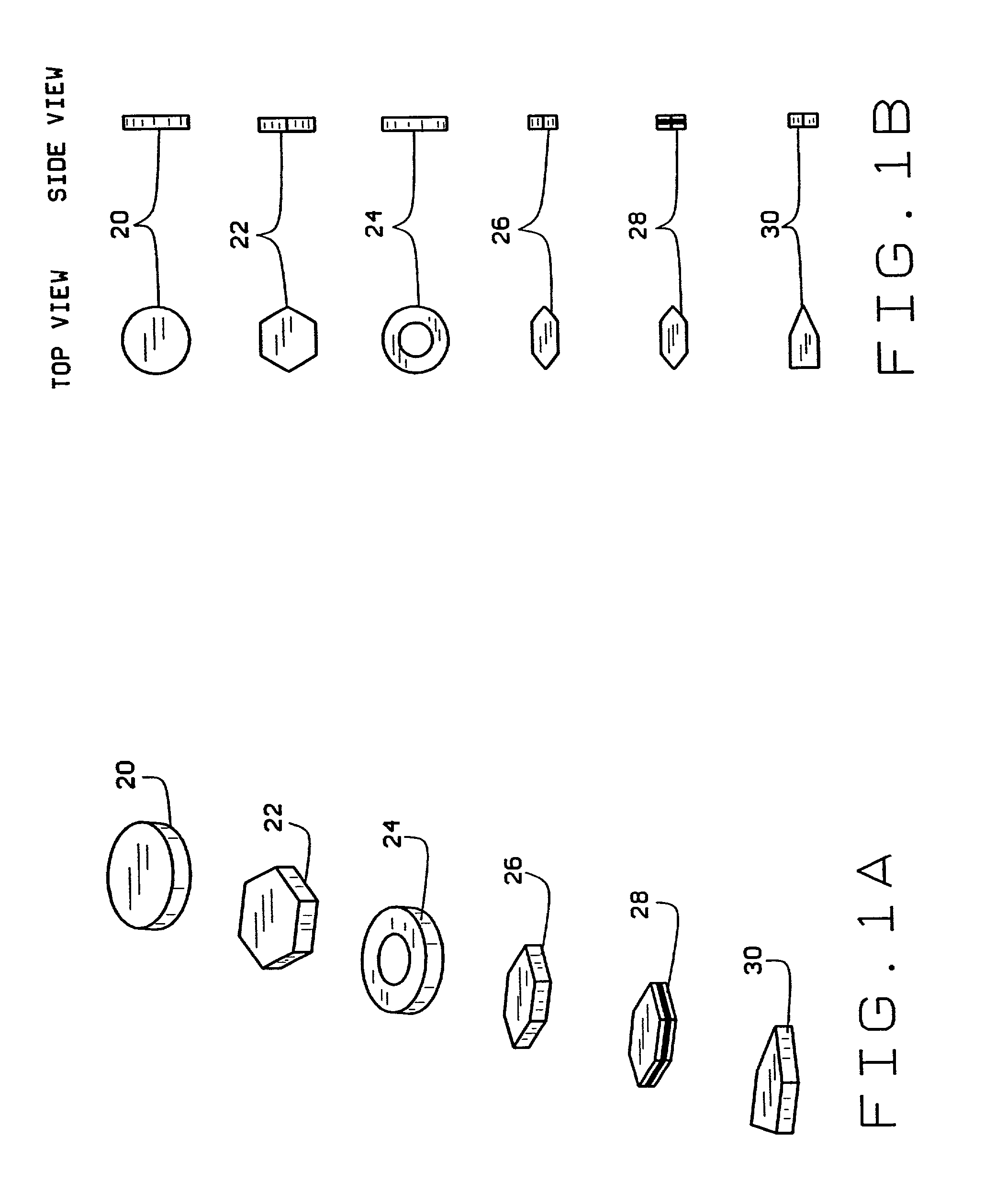
Designer particles of micron and submicron dimension
a technology of design particles and microns, applied in the direction of vacuum evaporation coating, fluid speed measurement, chemical vapor deposition coating, etc., can solve the problems of particle materials and processes that particle materials and processes cannot be produced in all sizes, and materials which may be utilized are process dependent, etc., to achieve uniform effects
- Summary
- Abstract
- Description
- Claims
- Application Information
AI Technical Summary
Problems solved by technology
Method used
Image

Examples
example 2
[0040] In a manner similar to example 1, Cu / Ni / Cu disks were fabricated. The diameter of the particles was 1 .mu.m, the thickness of the metal layers were 100 nm of Cu, 100 nm of Ni and 100 nm of Cu.
example 3
[0041] In a manner similar to example 2 (with no chromium predeposited), Si / Au / Si disks were made. Silicon and gold layers were deposited by electron beam evaporation in the CVC SC4500 combination thermal / e-gun evaporation system. The diameter of the particles was 1 .mu.m, the thickness of the layers were 20 nm of Si, 150 nm of Au and 20 nm of Si.
example 4
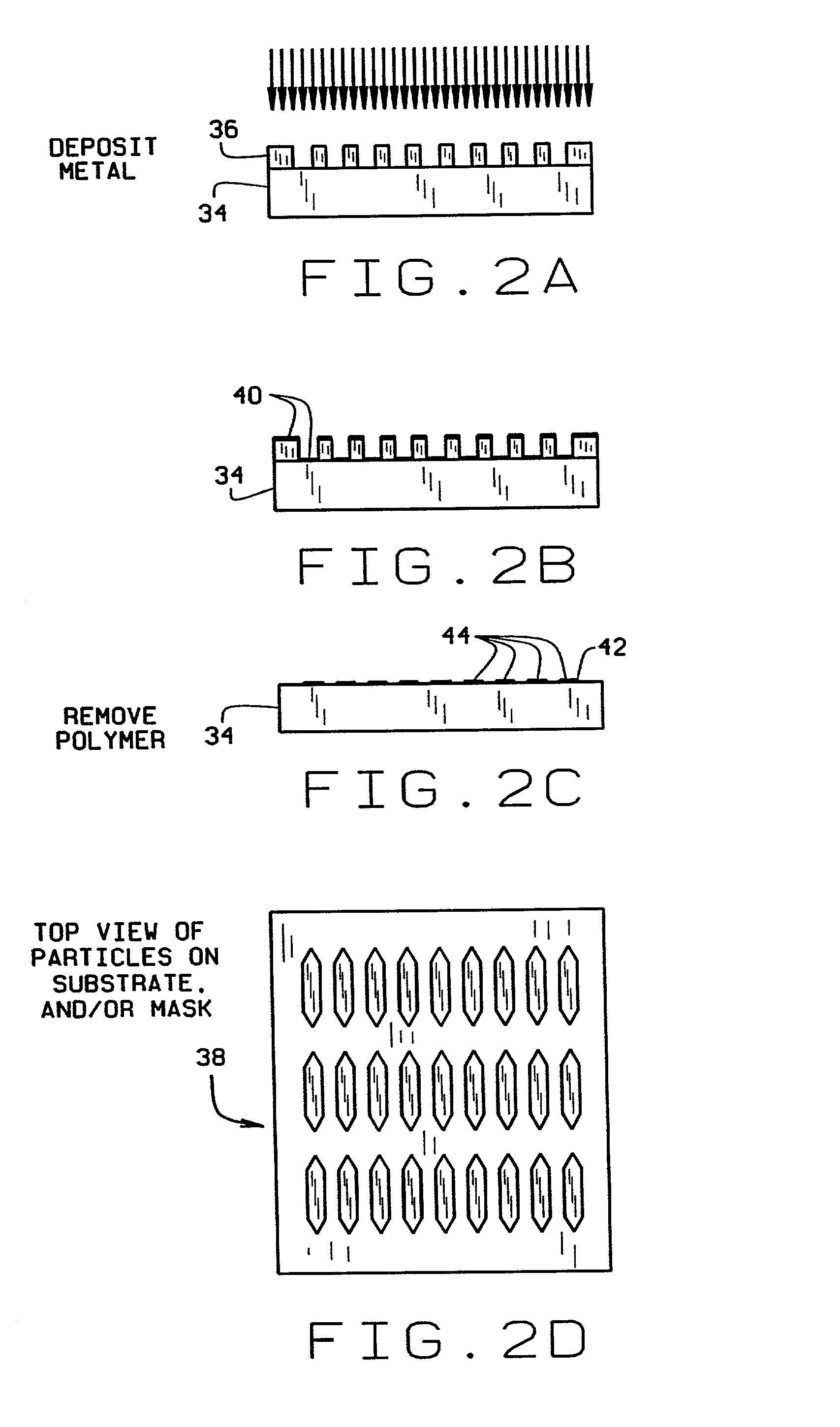
[0042] A mask for W disk fabrication was made in a manner similar to example 1. Due to the high temperature and the very slow rate of tungsten deposition in the system used, it was difficult to thermally deposit thick (>50 nm) layers onto a patterned wafer without damaging the photoresist. The following technique was used. A 200 nm layer of W was deposited by sputtering (CVC Sputter Deposition System) on the top of an Al "sacrificial" layer. 20 nm of Ta was predeposited onto the Si surface for better adhesion. The wafers were then primed by exposing them to hexamethyldisilazane in the YES oven at 90.degree. C. for 30 minutes.
[0043] The photoresist was deposited and developed as before but the photoresist pattern on the top of the W layer was now used as a protective mask for etching off some of the surrounding W. To obtain sharp profiles reactive ion etching in a CF.sub.4 plasma (RIE System, Applied Materials, California) was used. To lift off the particles, the Al "sacrificial" lay...
PUM
| Property | Measurement | Unit |
|---|---|---|
| width | aaaaa | aaaaa |
| width | aaaaa | aaaaa |
| size | aaaaa | aaaaa |
Abstract
Description
Claims
Application Information