
Apparatus and method for cryogenic inhibition of hyperplasia

a cryogenic inhibition and apparatus technology, applied in the field of apparatus and method for cryogenic inhibition of hyperplasia, can solve the problems of significant temperature transients, undesirable cell necrosis,

Inactive Publication Date: 2002-02-28
BOSTON SCI SCIMED INC
View PDF4 Cites 90 Cited by
  • Summary
  • Abstract
  • Description
  • Claims
  • Application Information

AI Technical Summary

Benefits of technology

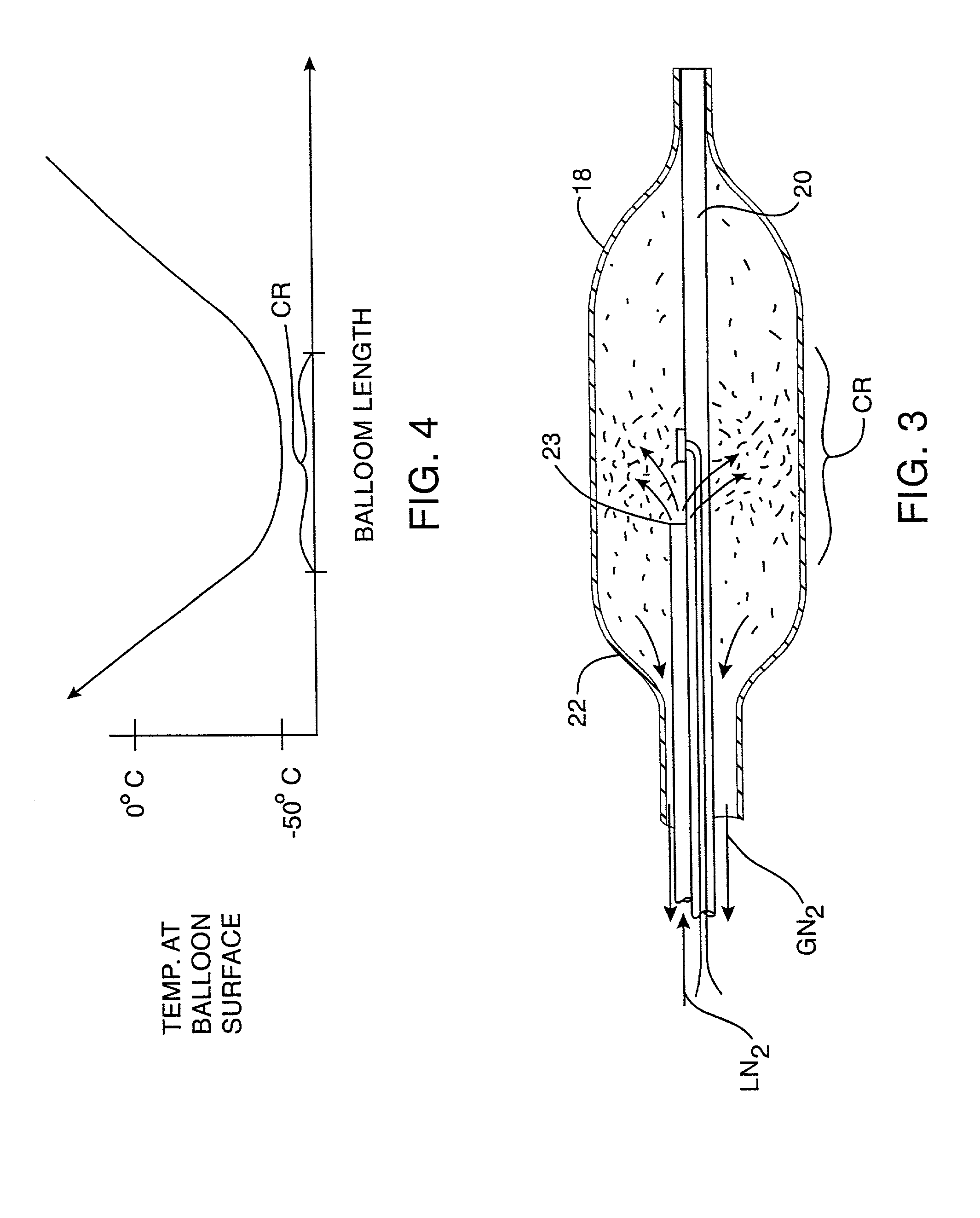
[0013] Methods according to the present invention comprise cooling an inner surface of the body lumen to a temperature and for a time sufficient to inhibit subsequent cell growth. Generally, the temperature at the tissue surface will be in a range from about 0.degree. C. to about -80.degree. C., the tissue surface temperature preferably being in a range from about -10.degree. C. to about -40.degree. C. In other embodiments, the temperature at the cell surface can be in the range from -20.degree. C. to -80.degree. C., optionally being from -30.degree. C. to -50.degree. C. The tissue is typically maintained at the described temperature for a time period in the range from about 1 to about 60 seconds, often being from 1 second to 10 seconds, preferably from 2 seconds to 5 seconds. Hyperplasia inhibiting efficacy may be enhanced by repeating cooling in cycles, typically with from about 1 to 5 cycles, with the cycles being repeated at a rate of about one cycle every 60 seconds. In the case of arteries, the cooling treatment will usually be effected very shortly after angioplasty, arthrectomy, rotational arthrectomy, laser angioplasty, stenting, or another primary treatment procedure, preferably within one hour of the primary treatment, more preferably within thirty minutes within the primary treatment, and most preferably immediately following the primary treatment.
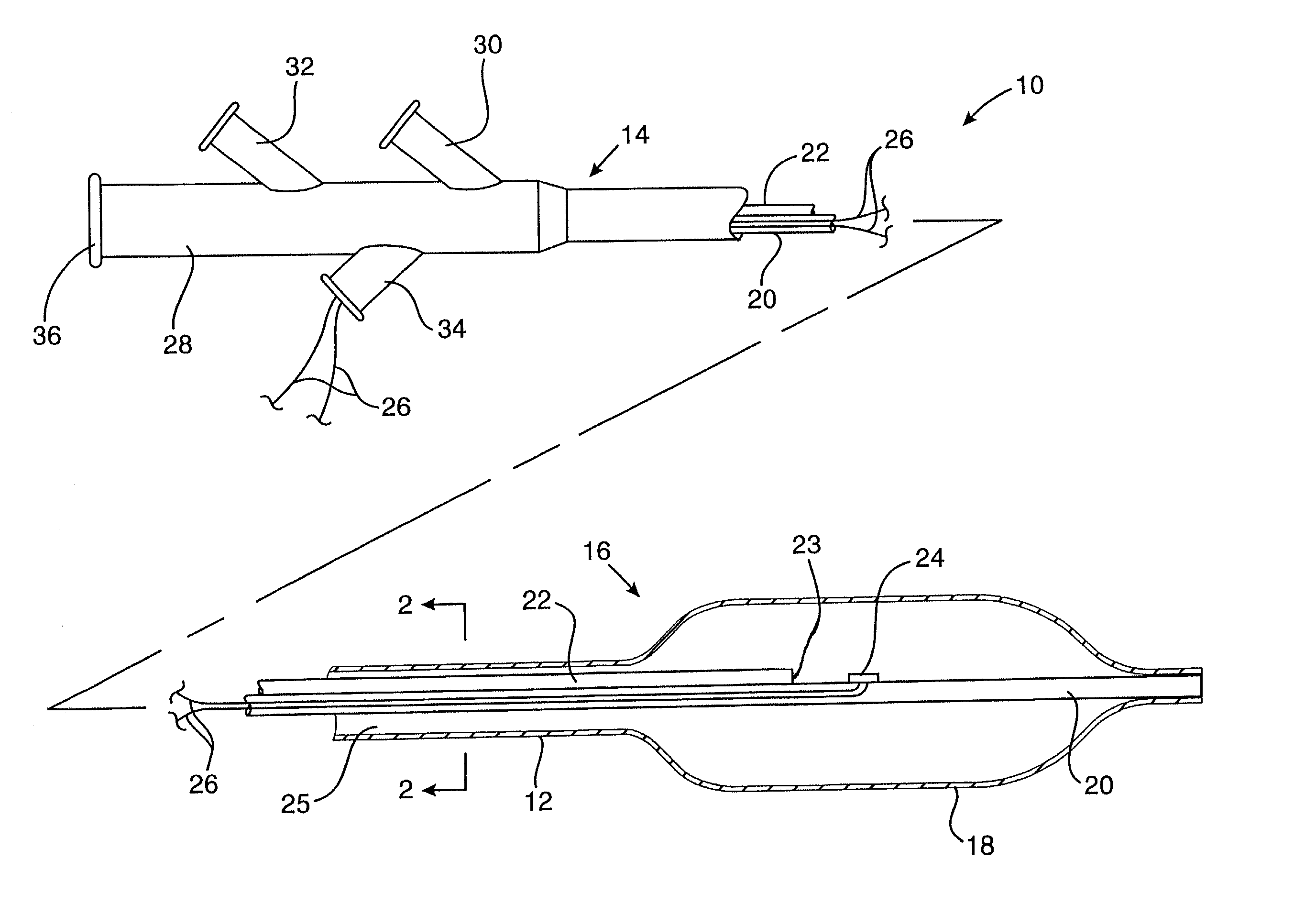
[0014] The methods of the present invention may be performed with cryosurgical catheters comprising a catheter body having a proximal end, a distal end, and a primary lumen therethrough. The primary lumen terminates in a Joule-Thomson orifice at or near its distal end, and a balloon is disposed over the orifice on the catheter body to contain a cryogenic fluid delivered through the primary lumen. Suitable cryogenic fluids will be non-toxic and include liquid nitrogen, liquid nitrous oxide, liquid carbon dioxide, and the like. By delivering the cryogenic fluid through the catheter body, the balloon can be expanded and cooled in order to effect treatments according to the present invention.
[0015] Preferably, the Joule-Thomson orifice will be spaced inwardly from each end of the balloon and the balloon will be sufficiently long so that the cooling of the balloon occurs primarily in the middle. The temperature of the proximal and distal ends of the balloon will thus be much less than that of the middle, and the ends will thus act as "insulating" regions which protect luminal surfaces and other body structures from unintended cooling. Preferably, the balloon has a length of at least 1 cm, more preferably at least 2 cm, and typically in the range from 3 cm to 10 cm. The orifice is usually positioned at least 0.5 cm from each end, preferably being at least 1 cm from each end in balloons which are 2 cm or longer.

Problems solved by technology

Particularly in the treatment of arteries following balloon angioplasty, cell necrosis may be undesirable if it increases the hyperplastic response.
There may be significant temperature transients when cryogenic cooling is first initiated from within the balloon catheter.

Method used


Image

  • Apparatus and method for cryogenic inhibition of hyperplasia
  • Apparatus and method for cryogenic inhibition of hyperplasia
  • Apparatus and method for cryogenic inhibition of hyperplasia

Examples


Embodiment Construction

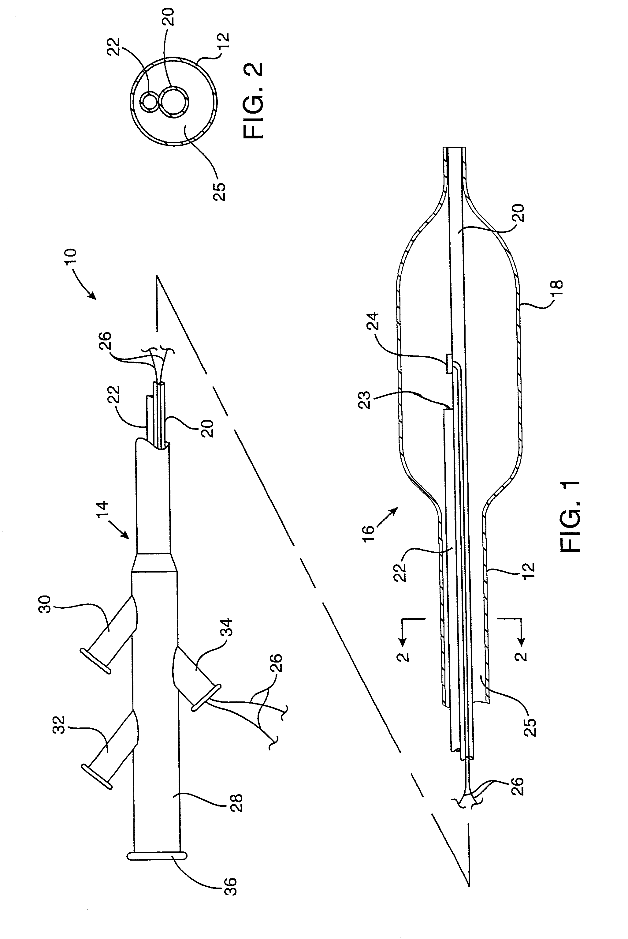
[0040] An exemplary cryosurgical catheter 10 constructed in accordance with the principles of the present invention is illustrated in FIGS. 1 and 2. The catheter 10 comprises a catheter body 12 having a proximal end 14, a distal end 16, and an inflatable balloon 18 disposed at the distal end. The balloon 18 is shown to be an integral extension of the catheter body 12, but such a structure is not required by the present invention. The balloon could be formed from the same or a different material and, in the latter case, attached to the distal end of the catheter body 12 by suitable adhesives, heat welding, or the like. The catheter body may be formed from conventional materials, such as polyethylenes, polyimides, and copolymers and derivatives thereof. The balloon may also be formed from conventional materials used for angioplasty balloons, typically being non-distensible, such as polyethylene terephthalate (PET).

[0041] Catheter 10 comprises a central shaft 20 which may be formed fro...


PUM


Abstract

Post-angioplasty hyperplasia in blood vessels is treated using a cryosurgical balloon catheter. The balloon catheter is positioned at a target region within the blood vessel, and the balloon inflated by expanding a cryogenic fluid, such as liquid nitrogen, across an expansion orifice into a balloon. The balloon will be constructed so that cooling is achieved primarily in the central regions of the balloon, with the proximal and distal regions being less cold and acting to insulate adjacent regions of the blood vessel from excessive cooling.

Description

CROSS-REFERENCES TO RELATED APPLICATIONS[0001] This application is a divisional of, and claims priority from U.S. patent application Ser. No. 09 / 203,011 filed Dec. 1, 1998, which is a continuation-in-part of, and claims the benefit of priority from, co-pending U.S. patent application Ser. No. 08 / 982,824, filed Dec. 2, 1997, the full disclosures of which are incorporated herein by reference.[0002] 1. Field of the Invention[0003] The present invention relates generally to apparatus and methods for inhibiting restenosis in arteries following angioplasty or other intravascular procedures for treating atherosclerotic disease. More particularly, the present invention relates to apparatus and methods for cryogenically treating the target site within a patient's vasculature to inhibit hyperplasia which can occur after such intravascular procedures.[0004] A number of percutaneous intravascular procedures have been developed for treating atherosclerotic disease in a patient's vasculature. The...

Claims


Application Information

Patent Timeline
IPC IPC(8): A61B17/00A61B17/22A61B18/00A61B18/02A61M25/00
CPCA61B18/02A61B2017/00292A61B2017/22001A61B2017/22002A61B2017/22051A61B2018/00196A61B2018/0022A61B2018/0212A61B2018/0262A61B2018/0275
Inventor JOYE, JAMESWILLIAMS, RONALD
Owner BOSTON SCI SCIMED INC
Learn More