

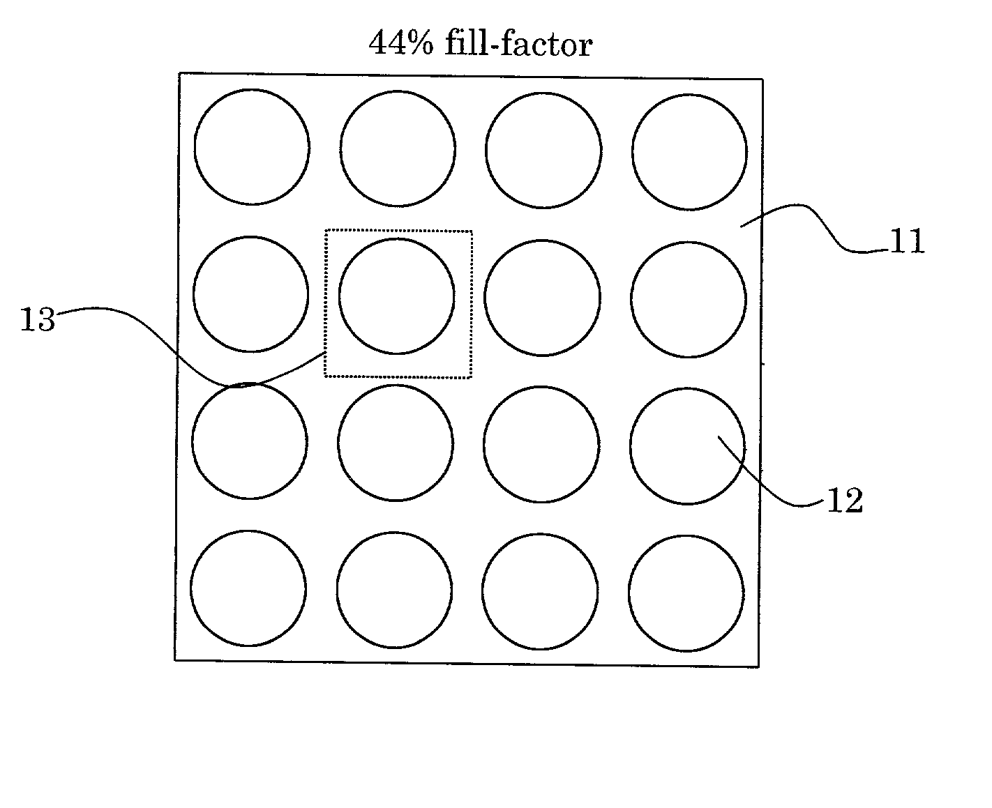
Microlens arrays having high focusing efficiency
a microlens array and high focusing efficiency technology, applied in the field of arrays of microlenses, can solve the problems of not being able to control the fusing of material at the internal boundary of the microlense, unable to obtain efficient closed-packed lens arrays using prior art fabrication methods, etc., to reduce the fill factor and the focusing efficiency of the array
- Summary
- Abstract
- Description
- Claims
- Application Information
AI Technical Summary
Benefits of technology
Problems solved by technology
Method used
Image

Examples
Embodiment Construction
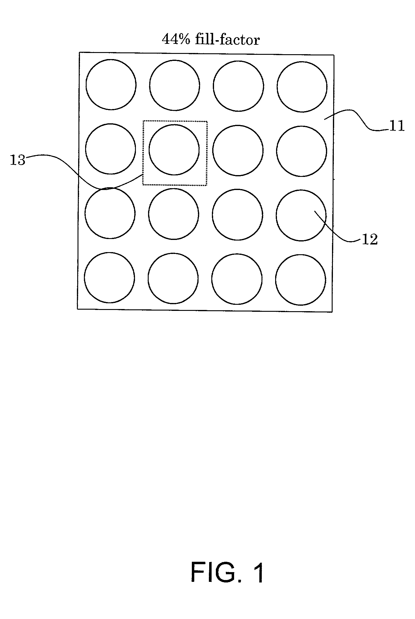
[0048] Referring now to the figures, FIG. 2 shows a photosensitive resist film 21 of low contrast deposited on a substrate 22 which is typically made of glass. The thickness of the film should be equal to or larger than the total depth span defined by the lens array. Depending on the total thickness of the array, the resist may require preliminary processing such as hardening.
[0049] After the initial resist processing, a laser beam is focused at the resist film and scanned along the surface so as to expose the whole resist surface, as indicated in FIG. 3. The intensity of the laser beam varies for every point in such a fashion that a latent image of the negative of the desired convex microlenses is imprinted in the resist in the form of a chemical transformation of the resist material.
[0050] To obtain a surface-relief structure the chemically modified resist film undergoes a development process, which consists of exposure to a solution of, for example, a standard alkali developer fo...
PUM
 Abstract
Description
Claims
Application Information