Injection molding apparatus for molding multi-layered article and method of injection-molding multi-layered article

a multi-layered article and injection molding technology, which is applied in the direction of dough shaping, application, manufacturing tools, etc., can solve the problems of destabilizing the amount of the first molten resin to be injected into the cavity, not necessarily having complete performance of the container formed of a biaxially oriented thermoplastic polyester resin composed mainly of pet resin, and affecting the taste of the content. , to achieve the effect of preventing the leakage of molten resin and poor durability

Inactive Publication Date: 2002-03-28
MITSUBISHI GAS CHEM CO INC
View PDF0 Cites 21 Cited by
  • Summary
  • Abstract
  • Description
  • Claims
  • Application Information

AI Technical Summary

Benefits of technology

[0083] The injection molding apparatus of the present invention is provided with the back flow means for allowing first molten resin in the first resin-flow-passage to flow into the second resin-flow-passage. When first molten resin is injected into the cavity, therefore, first molten resin (which has flowed into the second resin-flow-passage in a previous molding cycle) has been present in that portion of the second resin-flow-passage which is near the junction portion of the resin-flow-passages. Therefore, a phenomenon that first molten resin to be injected is mixed with second molten resin in the second resin-flow-passage in the vicinity of the junction portion can be prevented, and a phenomenon that second molten resin which is not in an injected state is taken into first molten resin which is being injected can be prevented. As a result, there can be reliably prevented a problem that second resin comes to exist on the surface of a multi-layered article.
[0084] In the method of injection molding a multi-layered article according to any one of the first to fourth aspects of the present invention, the injection molding apparatus of the present invention is used which is provided with the back flow means for allowing first molten resin in the first resin-flow-passage to flow into the second resin-flow-passage. When first molten resin is injected into the cavity in the step (A), therefore, first molten resin (which has flowed into the second resin-flow-passage in a previous molding cycle) has been present in that portion of the second resin-flow-passage which is near the junction portion of the resin-flow-passages. Therefore, a phenomenon that first molten resin to be injected is mixed with second molten resin in the second resin-flow-passage in the vicinity of the junction portion can be prevented, and a phenomenon that second molten resin which is not in an injected state is taken into first molten resin which is being injected can be prevented. As a result, there can be reliably prevented a problem that second resin comes to exist on the surface of a multi-layered article.
[0085] In the present invention, the back flow means constituted of a back flow control valve (a counter-flow control valve) can avoid an increase in the size of an injection molding apparatus and a complication of the apparatus, and prevents the leakage of molten resin from the resin-flow-passages. When a ball-type back flow control value is used as a back flow control valve, nothing but a ball moves under a fluid pressure, the back flow control valve is structurally simple, and neither a movable part nor a sliding part is present. The control of a fluid with a ball-type back flow control valve can be applied not only to the flow of a molten resin but also to the flow of each of a liquid and a gas. When a conventional shut-off valve is used, an electromagnetic valve or cylinder is operated with an external hydraulic pressure or air pressure, and the flow passage of a fluid is forcibly opened and closed with the rotation or reciprocal movement thereof. Therefore, the conventional shut-off valve is structurally complicated and has poor durability.

Problems solved by technology

However, a container formed of a biaxially oriented thermoplastic polyester resin composed mainly of PET resin does not necessarily have complete performances.
That is, when the content to be filled in a container is a food which requires high gas barrier properties of the container, the container formed of PET resin is insufficient in gas barrier properties against oxygen gas and carbon dioxide gas, and therefore, the container formed of PET resin has a defect that the taste of the content is impaired.
As a result, the amount of the first molten resin to be injected into the cavity is destabilized.
There is therefore caused a problem that the second resin which is not to compose the outermost layer of the multi-layered article comes to exist on the outermost layer surface.
However, there is caused the following problem.
That is, there is caused a problem that the second resin which is not to compose the outermost layer of the multi-layered article comes to exist on the outermost layer surface.

Method used


Image

  • Injection molding apparatus for molding multi-layered article and method of injection-molding multi-layered article
  • Injection molding apparatus for molding multi-layered article and method of injection-molding multi-layered article
  • Injection molding apparatus for molding multi-layered article and method of injection-molding multi-layered article

Examples


example 2

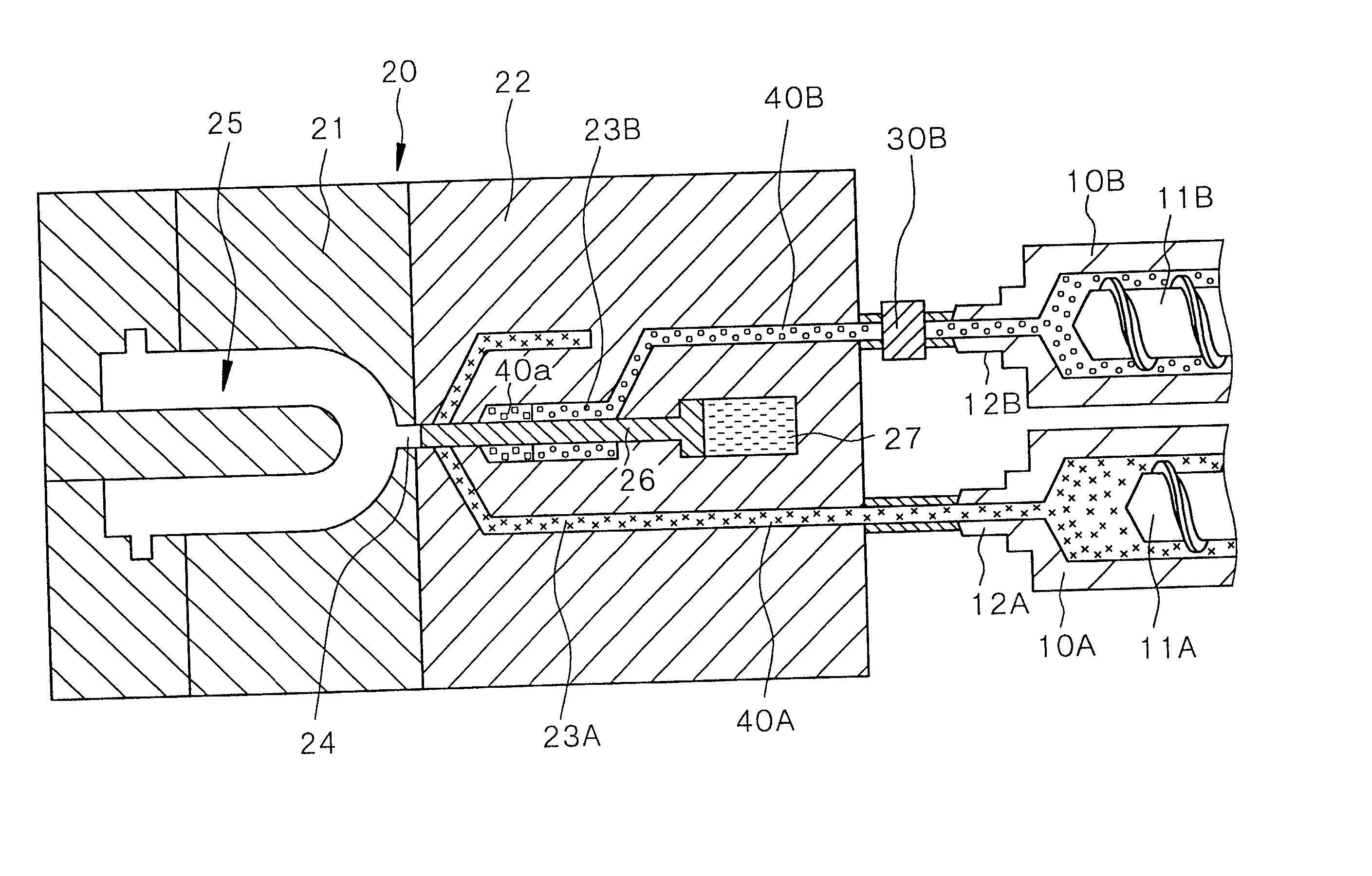
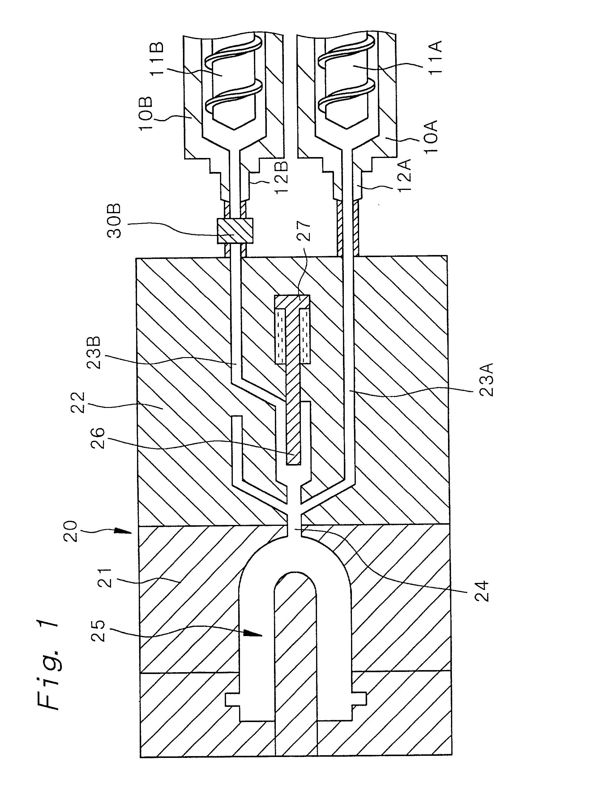
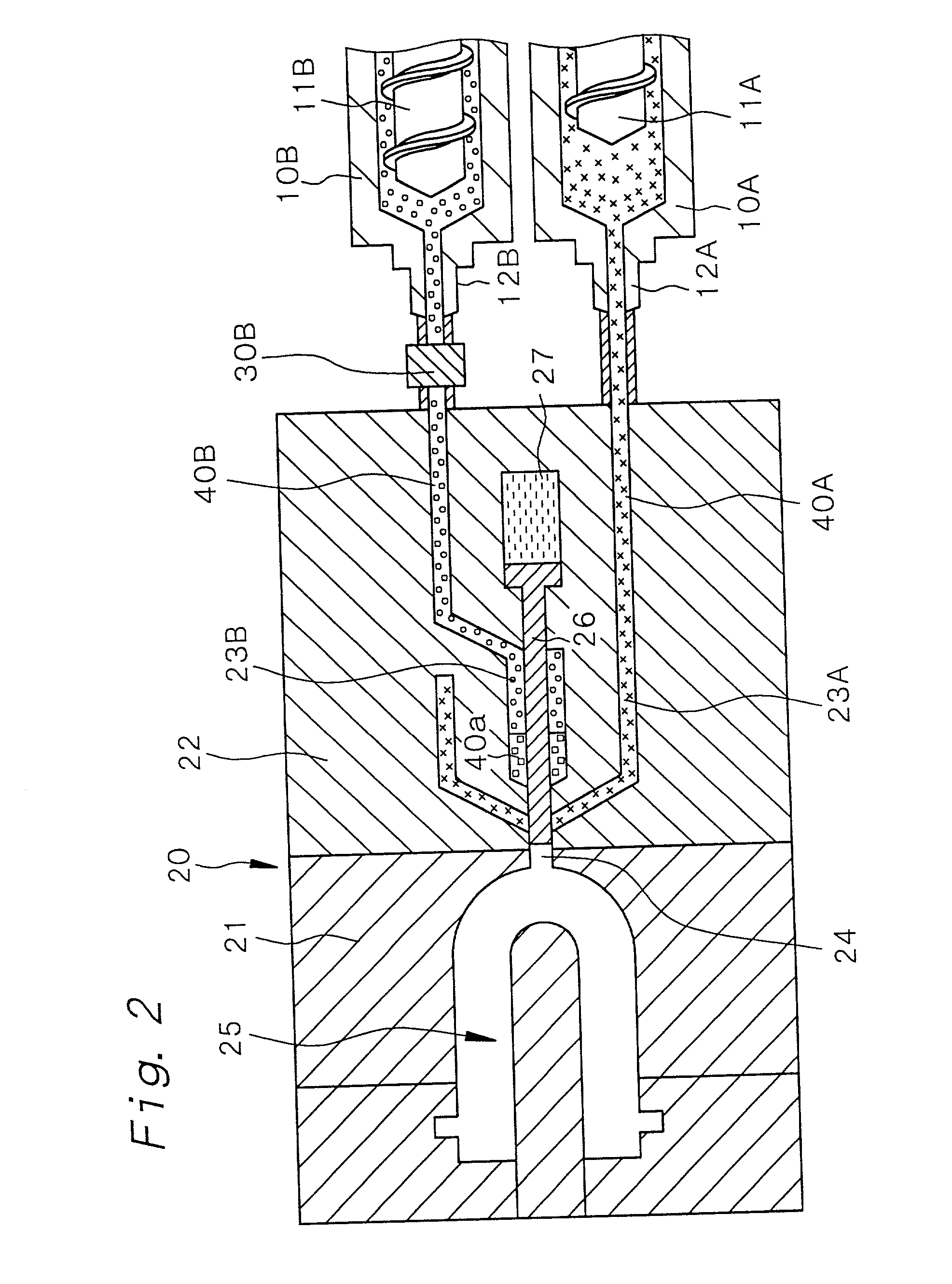
[0138] A polyethylene terephthalate resin having an intrinsic viscosity of 0.75 (PET resin, RT543C, supplied by Nippon Unipet K.K.) was used as a first resin 40A, and a poly-m-xylyleneadipamide resin having a relative viscosity of 2.7 (N-MXD6 resin, #6007, supplied by Mitsubishi Gas Chemical Co., Inc.) was used as a second resin 40B. PET resin, N-MXD6 resin and PET resin were alternately injected according to the steps explained in Example 1, to mold a five-layer-structured parison according to an alternate-injection molding method (the method of injection molding a multi-layered article according to the first aspect of the present invention). The parison had a length of 110 mm, a wall thickness of 4.5 mm and an outer diameter of 26.5 mm. A multi-layered bottle obtained from the above parison by a biaxial stretch blow molding method has dimensions of 200 mm in total length, 75 mm in outer diameter and 600 ml in volume.

[0139] Part of each of the first resin-flow-passage 23A and the s...

example 3

[0146] Parisons were molded using the same injection molding apparatus as that described in Example 2, except that the back flow means was replaced with a ball-type back flow control valve 30B having a ball 34 which had the same diameter as that of the ball 34 in the back flow control valve 30B used in Example 2 but was provided with a larger movement distance of the ball 34 than the back flow control valve used in Example 2.

[0147] Before injection molding, first molten resin 40a which flowed into the second resin-flow-passage 23B in a previous molding cycle was left in the second resin-flow-passage 23B in an amount equal to 15% of the volume of each cavity 25.

[0148] First, in the same manner as in [Step-100], first molten resin 40A (molten PET resin) was injected into each cavity 25 in an amount equal to 40% of the volume of each cavity 25. In this step, no first molten resin 40A flowed into the second resin-flow-passage 23B.

[0149] Then, in the same manner as in [step-110], second ...

example 4

[0152] An ethylene-vinyl acetate copolymer resin saponification product (EVOH, EVAL EF-E, supplied by Kuraray Co., Ltd.) was used in place of the N-MXD6 resin used as a second resin 40B in Example 2. The following Table 2 shows temperature conditions in Example 4. Injection molding was carried out by means of the same injection molding apparatus as that in Example 2, except that the back flow means was replaced with a ball-type back flow control valve 30 having a ball 34 which had the same diameter as that of the ball 34 in the back flow control valve 30B used in Example 3 but was provided with a larger movement distance of the ball 34 than the back flow control valve used in Example 3.

2 TABLE 2 Temperature of first molten resin 40A 270.degree. C. in injection cylinder 10A: Temperature of second molten resin 40B 230.degree. C. in injection cylinder 10B: Temperatures in first and second 270.degree. C. resin-flow-passages in hot runner block: Temperature of mold coolant 15.degree. C. ...


PUM

PropertyMeasurementUnit
Temperatureaaaaaaaaaa
widthaaaaaaaaaa

Abstract

An injection molding apparatus for injection molding a multi-layered article, which comprises; (a) a mold having a cavity block provided with a cavity and a hot runner block, (b) at least a first injection cylinder and a second injection cylinder, (c) a first resin-flow-passage for connecting an inside of the first injection cylinder and the cavity, and (d) a second resin-flow-passage for connecting an inside of the second injection cylinder and the cavity, the injection molding apparatus having a structure in which those portions of the first and second resin-flow-passages which are located within the mold are provided in the hot runner block, and the first resin-flow-passage and the second resin-flow-passage meet with each other in a junction portion upstream to a gate portion opened to the cavity, the injection molding apparatus being provided with back flow means for letting first molten resin in the first resin-flow-passage flow into the second resin-flow-passage after second molten resin is injected into the cavity through the second resin-flow-passage, the back flow means being operable with a pressure which the first molten resin in the first resin-flow-passage exerts on second molten resin in the second resin-flow-passage.

Description

BACKGROUND OF THE INVENTION AND RELATED ART[0001] The present invention relates to an injection-molding apparatus for molding a multi-layered article and a method of injection-molding a multi-layered article.[0002] In recent years, containers formed of thermoplastic resins are widely used as containers for cosmetics, foods, beverages and the like. The development of containers formed of a polyethylene terephthalate resin (to be sometimes abbreviated as "PET resin", hereinafter) in particular is rapidly advancing owing to improvements in biaxial orientation blow molding technology. However, a container formed of a biaxially oriented thermoplastic polyester resin composed mainly of PET resin does not necessarily have complete performances. That is, when the content to be filled in a container is a food which requires high gas barrier properties of the container, the container formed of PET resin is insufficient in gas barrier properties against oxygen gas and carbon dioxide gas, and t...

Claims


Application Information

Patent Timeline
Patent Type & Authority Applications(United States)
IPC IPC(8): B29C45/16
CPCB29B2911/1402B29B2911/14026B29B2911/1404B29B2911/1408B29B2911/14086B29B2911/14093B29B2911/1412B29B2911/14126B29B2911/14146B29B2911/14153B29B2911/14593B29B2911/14653B29B2911/14713B29C45/1603B29C45/1643B29C45/1646B29C2949/3018B29C2949/302B29C2949/3016B29C2949/28B29C2949/24B29C2949/22B29C2949/3028B29C2949/303B29C2949/3036B29C2949/3038B29C2949/082B29C2949/0811B29C2949/0829
Inventor MARUYAMA, KATSUYAHARA, TAKESHITERADA, YOSHIHIROOTA, TAKAO
Owner MITSUBISHI GAS CHEM CO INC
Why Eureka
Try Eureka