Compact sensor using microcavity structures

a microcavity structure and sensor technology, applied in the field of compact devices, can solve the problems of the noise floor of the detection system, and achieve the effects of strong signal, enhanced electric field of the probe beam, and stronger received signal

Inactive Publication Date: 2002-06-06
HRL LAB
View PDF2 Cites 182 Cited by
  • Summary
  • Abstract
  • Description
  • Claims
  • Application Information

AI Technical Summary

Benefits of technology

0039] If the substance to be detected is very dilute, its effects may fall below the noise floor of the detection system. One can address this problem by sampling the material many times with a single probe beam, such as in an optical cavity. Any absorption or phase shift of the probe beam will be effectively multiplied by the Q factor of the cavity, resulting in a stronger signal.
0040] To achieve cavity enhancement of a visible, infra-red, or millimeter wave signal does not necessitate having large cavity structures with precisely aligned mirrors. The same effects can be seen in many naturally occurring forms. For example, in surface-enhanced Ra

Problems solved by technology

These minuscule doses needed to achieve a lethal outcome lead to a challenging problem in detection, as the human detector may reveal symptoms at concentrations far below what a

Method used


Image

  • Compact sensor using microcavity structures
  • Compact sensor using microcavity structures
  • Compact sensor using microcavity structures

Examples


Embodiment Construction

1. Sensor in General

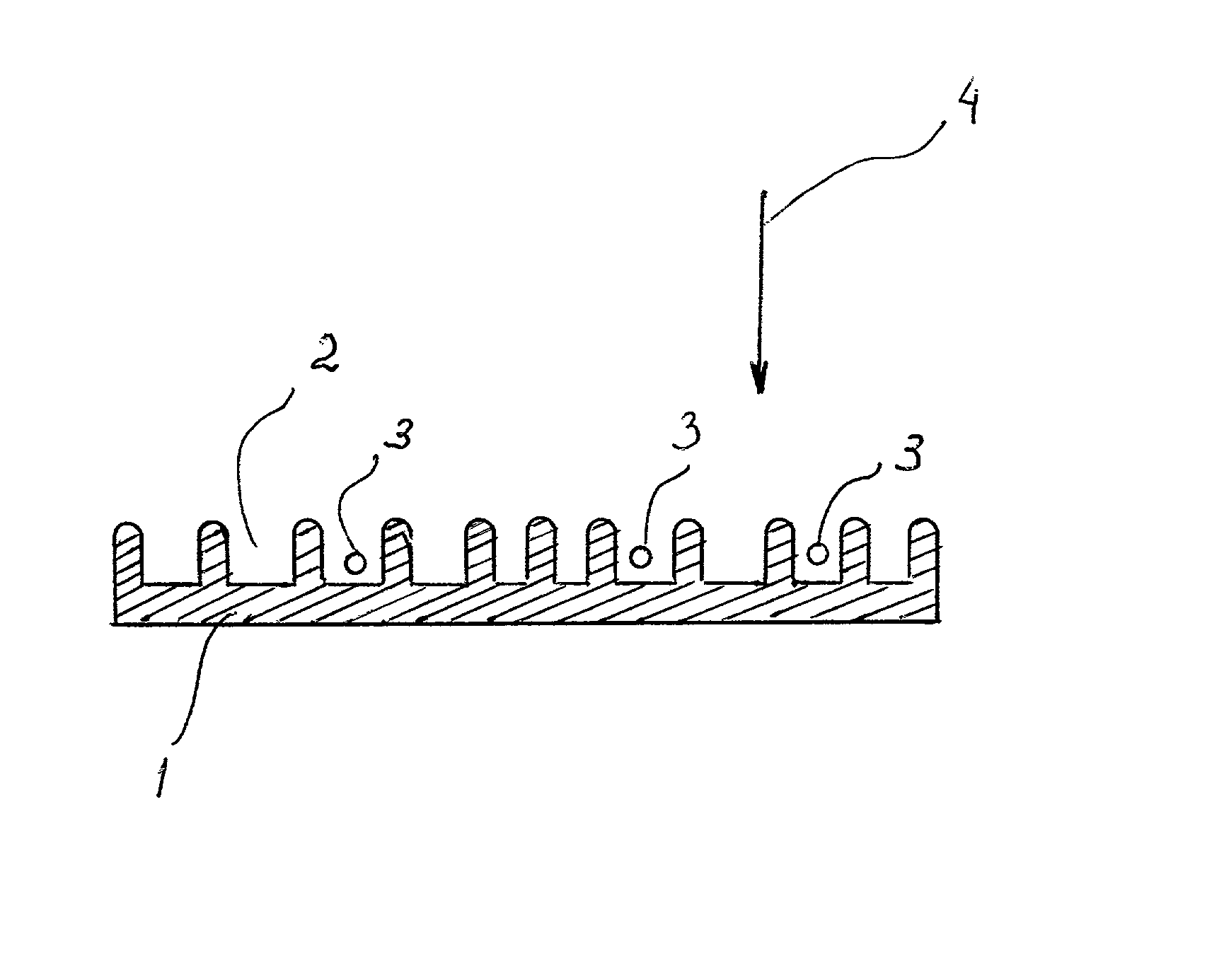
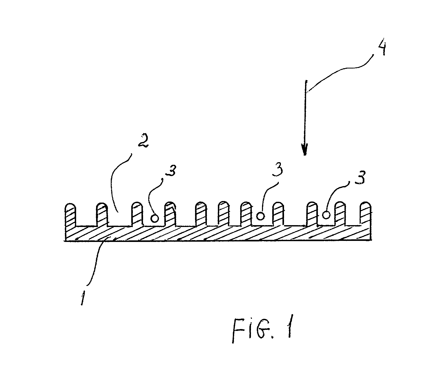
[0076] A simple example of an array of microcavities is shown in FIG. 1. A metal or dielectric surface 1 is textured with a lattice to form microcavities 2, into which particles of material to be detected 3 can fall. Due to the field enhancement inside the cavity 2, the absorption of the probe beam 4 is much greater than it would be if the particle were simply in a free space or on a smooth surface, as explained in more detail below.

[0077] The basic principle upon which this invention is based, is the principle of enhancement of electromagnetic field by an array of microcavities and it can be explained as follows. When a chemical compound enters one of the microcavities, it feels a much greater applied electromagnetic field when the probe beam is near the resonance frequency of the cavities. In effect, the probe beam samples the chemical compound multiple times. The magnitude of this enhancement is proportional to the Q of the cavities. This is similar to the enh...


PUM


Abstract

A compact sensor for detection of chemical and/or biological compounds in low concentration. The sensor comprises electromagnetic microcavities. The agent to be detected passes the microcavities, is absorbed and/or absorbed by the microcavities, and modifies the electromagnetic field inside the microcavities. After the agent has been adsorbed and/or absorbed, a probe beam is applied to the microcavities. The change of electromagnetic field is detected by the detector, and the frequency of the probe beam at which the resonance is observed, is indicative of a particular agent being present. A method for detecting chemical and/or biological compounds using the sensor.

Description

I. BACKGROUND OF THE INVENTION[0001] 1. Field of the Invention[0002] This invention relates to the field of compact devices for remotely detecting the presence of chemical or biological agents using an electromagnetic microcavity element or an array or assembly of microcavity elements.[0003] More particularly, it pertains to the devices which detect chemical or biological agents using a state-selective material which is placed inside or surrounding the microcavities. The complex dielectric constant of the microcavities is modified by the presence of the compound to be detected. This invention allows one to detect the presence of chemical and biological agents even at a very low concentration.[0004] In other terms, this invention pertains to a photonic bandgap crystal, the dispersion characteristic of which are modified by the introduction of a chemically or biologically active material, followed by the detection of such modification. The changes in the cavity in the presence of the ...

Claims


Application Information

Patent Timeline
IPC IPC(8): G01N22/00B81B1/00G01N21/03G01N21/27G01N21/33G01N21/35G01N21/55G01N21/77G01N33/487G01N33/543
CPCG01N21/031G01N21/7746G01N21/774
Inventor PEPPER, DAVID M.SIEVENPIPER, DANIEL
Owner HRL LAB
Why Eureka
Try Eureka