Catalytic separator plate reactor and method of catalytic reforming of fuel to hydrogen

Inactive Publication Date: 2002-06-13
CATALYTICA ENERGY SYST
View PDF10 Cites 137 Cited by
  • Summary
  • Abstract
  • Description
  • Claims
  • Application Information

AI Technical Summary

Benefits of technology

[0013] The flow paths are configured in the reactor apparatus with the first set of flow channels adjacent to and in intimate heat exchange with the second set of flow channels through a common channel wall. It is preferred that the catalytic surfaces in each cell be in opposed relationship. That is, the catalyst surface in one channel-type reaction zone is directly on the opposite side of a common separator plate on the other side of which is disposed the catalytic surface of the other channel / reaction zone, such that the exothermic heat of reaction generated by the catalyst in the first set of flow channels is conductively transferred directly through the separator plate to the catalyst for the endothermic reaction in the second set of flow channels. In a preferred embodiment of this invention, the flow-through reactor is used to carry out simultaneous catalytic combustion of methane and catalytic methane reforming. The catalyst concentration / catalytically active surface area is balanced between the two sets of channels such that the heat generated by the exothermic reaction is entirely consumed by the endothermic reaction, thereby avoiding the presence of hot spots or heat imbalances on the catalytic surfaces that may deactivate or sinter if exposed to high temperatures.

Problems solved by technology

One undesired consequence of those high burner temperatures is the production of NO.sub.x in the combustion flue gases.
In addition, because a gaseous stream transfers the heat of reaction, the volume of the furnace is necessarily large.
Equally important, such industrial reformers can not be scaled to smaller sizes for modular portable units in order to provide sufficient hydrogen-rich gas for fuel cells or chemical reaction processes.
Because of the safety and volume constraints, high purity hydrogen in pressurized tanks is presently not desirable for vehicle fuel cells.
These prior art plate reactors to date have not been widely adopted by the art, and they appear to present the following types of concerns and problems: In U.S. Pat. No. 5,015,444 of Koga et al., the combustion and reforming catalysts are in the form of powders or pellets filling the gaps between plates.
This should result in a more compact design; however, this reactor is just a laboratory-scale unit that does not scale-up well.

Method used


Image

  • Catalytic separator plate reactor and method of catalytic reforming of fuel to hydrogen
  • Catalytic separator plate reactor and method of catalytic reforming of fuel to hydrogen
  • Catalytic separator plate reactor and method of catalytic reforming of fuel to hydrogen

Examples


example 1

[0065] Production of Separator Plates Coated with a Pd Catalyst on a Zirconia Support.

[0066] A Pd-impregnated zirconia sol was prepared following the procedure taught in U.S. Pat. No. 5,259,754, Example 1, the disclosure of which is hereby incorporated by reference. An Fe / Cr / Al metal foil was oxidized in ambient air at 900.degree. C. for ten hours to form alumina whiskers on the foil surface. The colloidal Pd / ZrO.sub.2 sol was sprayed onto both sides of the corrugated foil. The coated foil was then heat treated for ten hours in air at 700.degree. C. The final foil contained 10 mg Pd / ZrO.sub.2 / cm.sup.2 foil surface, and this dual-surface catalytic foil is used to form separator plates in a reactor design of this invention.

example 2

[0067] Reactor Operation

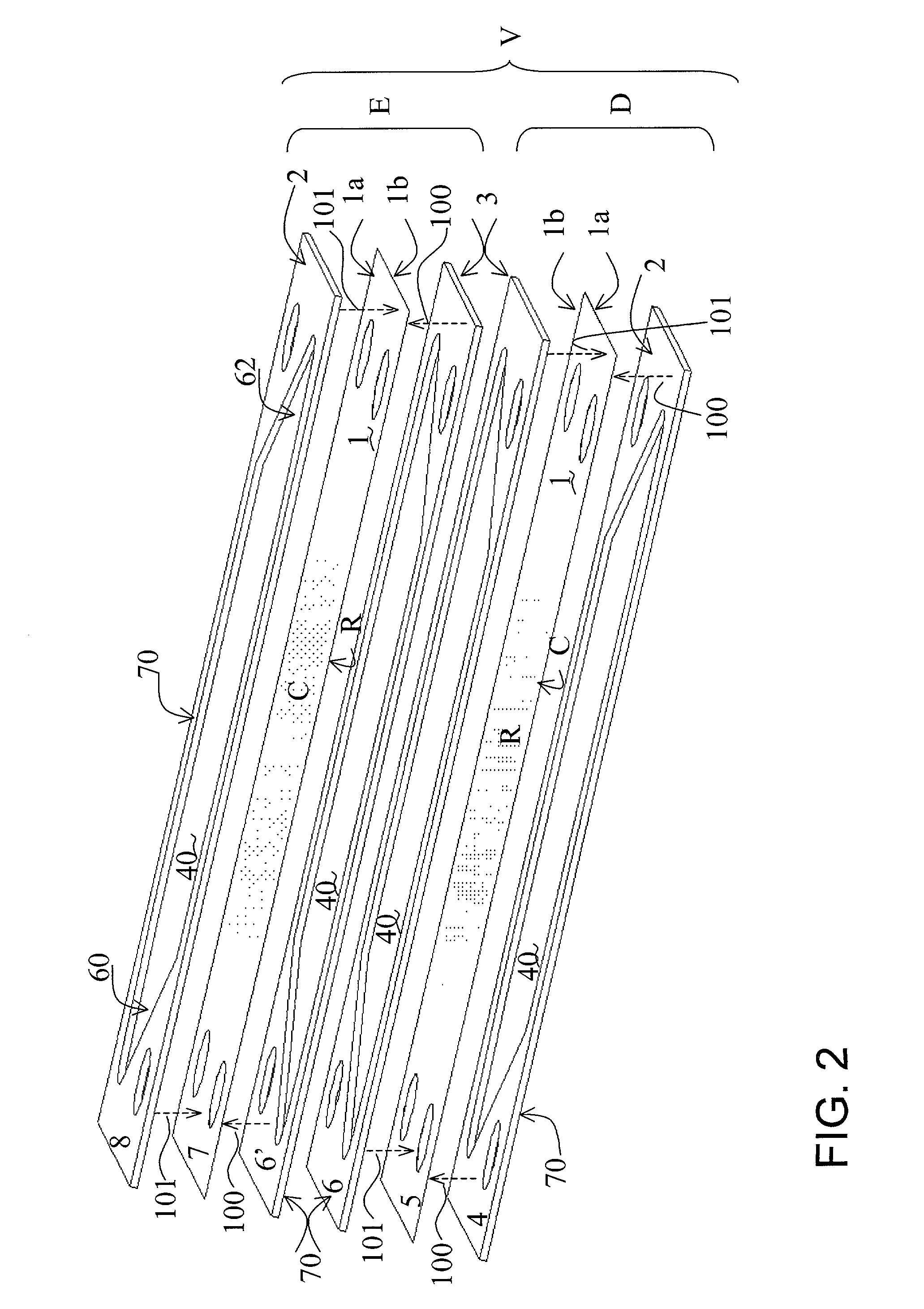
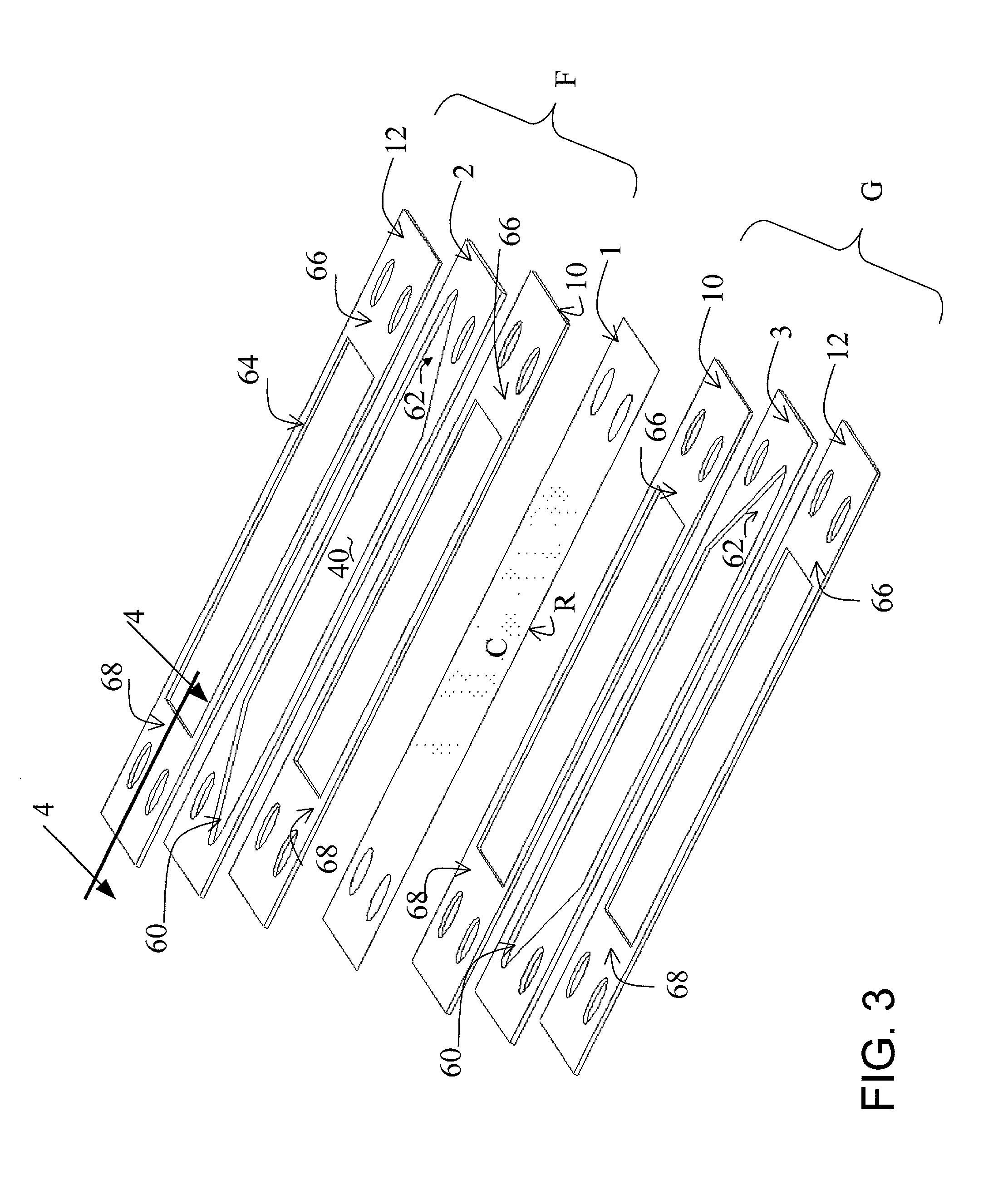
[0068] Two separator plates constructed of the foil prepared in accordance with the procedure of Example 1 were employed in a reactor of the design illustrated in FIG. 7 (described above) and tested. Flow-directing devices illustrated in FIG. 6 were inserted in the reforming and combustion channels. The air flow rate in the test was 100 SLPM; the fuel was natural gas supplied at a flow rate of 3 SLPM both on the combustion and reforming channels, the steam / methane molar ratio was 3.0, and the steady state preheat temperature for all inlet streams was 485.degree. C. The performance of those plates is shown in FIG. 8. Solid trace lines in this figure denote reformer zone inlet and outlet temperatures versus runtime. The Temperatures were measured in the reforming channel at the upstream and downstream edges of the catalyst coating R (see positions 60 and 62, respectively, in FIG. 6). An overlay plot shows the conversion of methane versus runtime, the diamonds r...

example 3

[0070] Production of Separator Plates Coated with a Combustion Catalyst on One Side and a Reforming Catalyst on the Opposite Side.

[0071] In this example, the combustion catalyst is a palladium catalyst on a zirconia support coated on one side of a foil separator plate as indicated in Example 1. The reforming catalyst is a rhodium catalyst on a zirconia-modified support coated on the other side of the same foil in process steps as follows: ZrO.sub.2 powder (modified by the addition of ceria and lanthana) was impregnated with a solution of RhCl.sub.3. The final Rh loading was 5 wt %. The Rh-impregnated zirconia paste was dried at 120.degree. C. overnight. It was then heat treated at 200.degree. C. for 2 hrs followed by heat treatment in ambient air at 500.degree. C. for 4 hrs. This solid material was mixed with water acidified with sulfuric acid to a pH of about 3, and ball milled in a polymer lined ball mill using a zirconia grinding media for ten hours. This colloidal Rh / ZrO.sub.2 s...


PUM

PropertyMeasurementUnit
Timeaaaaaaaaaa
Temperatureaaaaaaaaaa
Flow rateaaaaaaaaaa

Abstract

Modular, stackable, flow-through plate or channel reactor units for continuous, low temperature, catalytic reactions of two separate process reaction streams; typically the first is an exothermic combustion process and the second, an endothermic reforming process. Each reactor unit comprises two separate sets of flow channels or slot-type reaction zones formed in flow plates located between spaced, thin metal, highly heat-conductive metal foil or platelet separator walls, adjacent reactors in a stack including a common, medially located, bi-catalytic separator plate, i.e., a separator plate having on opposed surfaces the same or different catalysts selected for the particular reaction taking place in the adjacent reactor zone. Each flow plate has a relieved medial area defining the reaction zone, the side walls of which are the catalyst coated separator platelets. A separator platelet thus separates two adjacent reaction zones, one on each side and functions to transfer heat from the combustion occurring at the catalyst surface in the combustion zone directly to the reforming catalyst coated on the opposed surface. The reaction zones may include structures such as grooved plates or packed spheres to direct the feedstock gases to the catalyst coated on the platelet surfaces. Support frames, gaskets, manifolding, insulating spacers, end plates and assembly hardware and methods are also disclosed. Multiple modular reactor units or cells may be stacked to provide a reactor of any desired throughput capacity and portability. The invention also comprises methods for the catalytic reforming of hydrocarbon fuels for the production of synthesis gas or hydrogen employing the bi-catalytic reactor of the invention.

Description

[0001] The invention relates to plate or channel-type reactors using integrated bi-catalytic heat transfer separator walls, each wall surface containing or having coated thereon a selected catalyst. The reactor provides for continuous and simultaneous reaction of two different process reaction streams in the channels defined between the walls, wherein a first process reaction stream undergoes high temperature exothermic reaction in a first channel and a second process reaction stream undergoes an endothermic heat-consuming reaction in a second channel separated from the first by the heat transfer separator wall. The heat produced by catalytic oxidation of fuel in the first channel is transferred to the second channel where a catalytic reforming reaction takes place. Multiple modular catalyst coated separator wall units or cells may be stacked to provide a reactor of any desired throughput capacity and portability. This invention also comprises methods for the catalytic reforming of ...

Claims


Application Information

Patent Timeline
IPC IPC(8): B01J19/24B01J23/44B01J23/46B01J35/04B01J37/02C01B3/32C01B3/38C01B3/40F28D9/00F28F3/02H01M8/06
CPCB01J37/0248B01J37/0226B01J2219/2458B01J2219/2459B01J2219/2465B01J2219/2466B01J2219/2475B01J2219/2479B01J2219/2486B01J2219/2493B01J2219/2495B01J2219/2496B01J2219/2497B01J2219/2498C01B3/323C01B3/326C01B3/384C01B3/40C01B2203/0233C01B2203/06C01B2203/066C01B2203/0811C01B2203/0822C01B2203/085C01B2203/0866C01B2203/1017C01B2203/1035C01B2203/1047C01B2203/1052C01B2203/1064C01B2203/1082C01B2203/1211C01B2203/1241C01B2203/143C01B2203/80C01B2203/82F28D9/005F28D9/0075F28F3/02F28F3/025H01M8/0606H01M8/0625Y02E60/50B01J19/2485B01J19/249B01J23/44B01J23/464B01J35/04B01J2219/2453Y02P20/52Y02P20/10Y02P70/50B01J35/56
Inventor LOFFLER, DANIEL G.FAZ, CARLOS F.SOKOLOVSKII, VALERYIGLESIA, ENRIQUE
Owner CATALYTICA ENERGY SYST
Why Eureka
Try Eureka