
Cleaning tape

a technology of cleaning tape and tape body, which is applied in the field of cleaning tape, can solve the problems of reducing the reproduction output, affecting the accurate traveling of the tape, and unable to achieve sufficient reproducing outpu

Inactive Publication Date: 2002-07-04
HITACHT MAXELL LTD
View PDF1 Cites 28 Cited by
  • Summary
  • Abstract
  • Description
  • Claims
  • Application Information

AI Technical Summary

Problems solved by technology

If such stains are left uncleaned, they will cause various problems such that they will interfere with the accurate traveling of the tape or decrease a reproduction output.
Otherwise, a sufficient reproducing output cannot be attained.
However, the MR head causes electrostatic breakdown when a material largely charged is in contact with the MR head, while the magnetic field from the tape is disordered with the magnetic field generated with an electric current from the magnetic head to the tape so that noise is generated in the MR head when a material having excessively high conductivity is in contact with the MR head.
In either case, the MR head cannot function normally.
In spite of the decrease of the recording wavelength and the promotion of the thinning and elongation of the tape as the medium in the field of magnetic recording in these years, the conventional cleaning tape cannot cope with such technical progresses and changes.
For example, one problem is the conductivity of the cleaning tape.
Therefore, the conventional cleaning tape may cause the electrostatic breakdown caused by the contact with the MR head.
The conventional cleaning tape may unevenly abrade the magnetic head because of the deterioration of the contact of the tape with the head due to the thinning of the tape.
However, since the cleaning tape has the larger abrasion property than the magnetic tape, simple thinning of the cleaning tape may lead to the uneven abrasion of the magnetic head because of the deterioration of the contact of the cleaning tape with the head caused by the thinning of the cleaning tape.

Method used

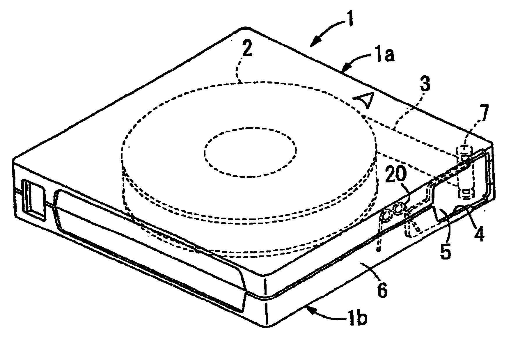
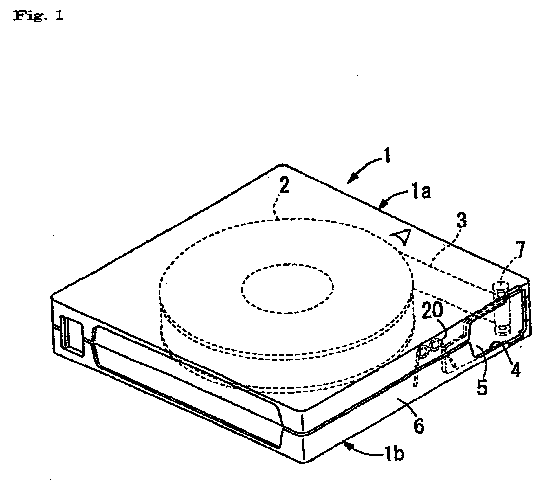

Image

  • Cleaning tape
  • Cleaning tape

Examples


example 1

[0088] Preparation of Coating for Primer Layer

[0089] The following components were provided for the preparation of a coating for a primer layer:

[0090] (1)

1 (1) Iron oxide powder (particle size 0.11 .times. 0.02 .mu.m) 60 parts Alumina (degree of alphatization: 50%; 10 parts particle size: 0.07 .mu.m) Carbon black (particle size: 25 nm; 30 parts DBP oil absorption: 50 cc / 100 g) Stearic acid 2.0 parts Vinyl chloride-hydroxyproyl acrylate copolymer 10 parts (-SO.sub.3Na content: 0.7 .times. 10.sup.-4 eq. / g) Polyester polyurethane resin 4.5 parts (Tg: 40.degree. C.: -SO.sub.3Na content: 1 .times. 10.sup.-4 eq. / g) Cyclohexanone 25 parts Methyl ethyl ketone 40 parts Toluene 10 parts (2) Butyl stearate 1 part Cyclohexanone 70 parts Methyl ethyl ketone 50 parts Toluene 20 parts (3) Polyisocyanate (Coronate L available from 4.5 parts Nippon Polyurethane Co., Ltd.) Cyclohexanone 10 parts Methyl ethyl ketone 15 parts Toluene 10 parts

[0091] The components of the group (1) were kneaded with a kn...

examples 2-6

[0100] A cleaning tape of each of Examples 2-7 was produced in the same manner as in Example 1 except that the amount of carbon black and the thickness of the cleaning layer, the kind of the nonmagnetic support and the presence of the primer layer were changed as shown in Table 1.


PUM

PropertyMeasurementUnit
surface roughness Raaaaaaaaaaa
Young's modulusaaaaaaaaaa
total thicknessaaaaaaaaaa

Abstract

A cleaning tape for a magnetic head system having a magnetoresistance effect head as a reproducing head, comprising a nonmagnetic support, and a cleaning layer containing a magnetic powder and a binder formed on one surface of said support, wherein said cleaning layer has a specific surface resistivity of 3x10³ to 5x10⁸ OMEGA / cm2, does not cause performance failure due to the electrostatic breakdown of the magnetic head or the generation of an electric current, which does not cause performance failure due to electrostatic breakdown of a magnetic head or the generation of an electric current.

Description

[0001] The present invention relates to a cleaning tape for cleaning a magnetic head installed in magnetic recording-reproducing equipment.PRIOR ART[0002] When a magnetic tape is traveled in magnetic recording-reproducing equipment for audio use, video use or computer use, stains tend to adhere to a surface (in contact with the magnetic tape) of a magnetic head (hereinafter sometimes simply referred to as "head") or tape-traveling systems such as guide rolls. If such stains are left uncleaned, they will cause various problems such that they will interfere with the accurate traveling of the tape or decrease a reproduction output. Thus, the head and the tape-traveling system should be periodically cleaned to avoid such problems and maintain the reliability of the magnetic recording-reproducing equipment.[0003] A cleaning tape used for such a cleaning purpose (herein a dry-type cleaning tape using no organic solvent) comprises a nonmagnetic support having, on one surface thereof, a cle...

Claims


Application Information

Patent Timeline
Patent Type & Authority Applications(United States)
IPC IPC(8): G11B5/41G11B23/04G11B23/107
CPCG11B5/41G11B23/049G11B23/107
Inventor MISAWA, YUJI
Owner HITACHT MAXELL LTD
Learn More