Optical parametric devices and methods for making same

a technology parametric devices, applied in the field of optical parametric devices, can solve the problems of inability to deliver large bandwidth, inability to achieve large bandwidth, etc., to achieve the effect of improving efficiency and bandwidth

Inactive Publication Date: 2002-09-12
UNIV OF SOUTHAMPTON
View PDF0 Cites 22 Cited by
  • Summary
  • Abstract
  • Description
  • Claims
  • Application Information

AI Technical Summary

Benefits of technology

[0026] Through the use of a poled holey fiber of suitable hole structure, it is possible to increase the SH efficiency .eta. as defined in Equation (1) in comparison with poled conventional (non-holey) fiber. One factor contributing to the high efficiency is the increase in the bandwidth-length product, which can be order of magnitude greater than for conventional fiber. Another factor contributing to the high efficiency is the ability of a holey fiber to provide a low fundamental mode area and a low SH mode area combined with good overlap between the fundamental mode and the SH mode. It is the combination of properties relating to mode area and SH bandwidth, each of which can be individually tailored in a holey fiber structure, that together allow a high efficiency .eta. to be achieved.
[0027] Another important factor is the ability in holey fiber structures to control dispersion properties. As well as allowing control of the linear dispersion, the microstructuring with holes can provide a low value of the group velocity mismatch GVM=(d.beta. / d.omega.).sub..omega.1-- (d.beta. / d.omega.).sub..omega.2 and higher order dispersion terms. A low value of GVM is important in determining phase matching properties of processes that involve significantly different wavelengths.
[0035] Further studies applying the theory of reference [9] have been carried out which indicate that the desired combination of single mode operation, broad bandwidth and good efficiency is achievable with a wide variety of hole structures. It is possible to calculate the relevant device parameters for any proposed hole structure using the theory of reference [9]. In that way, a suitable hole structure can be decided upon prior to fabrication.
[0040] A particular advantage of the optical poling method, as opposed to more conventional thermal poling, is that no electrode structuring is required. Continuous electrodes can be used. This is important, since continuous electrodes can be conveniently arranged embedded in the holey fiber structure. The electrodes may be inserted after drawing the holey fiber, or may be formed integrally with the holey fiber during the fiber drawing process. In this way, it is possible to place the electrodes close together straddling the optically active area of the waveguide where the mode is confined so that large electric fields can be generated in this region to provide good poling.

Problems solved by technology

These prior art periodically poled ferroelectrics waveguides and glass fibers thus cannot deliver the large bandwidth that is important to ensure stable operation of SHG devices (for example temperature stability when high power is involved) or for SHG devices operating in the pulsed regime where one requires that interaction occurs for all the spectral components of the pulse.
The resulting efficiency is however small compared to that achievable for the same device length with a periodic QPM structure due to a reduction of the effective interaction length L.
This method has the drawback that longer waveguides are needed to achieve similar efficiency with respect to the former situation where a pump at twice the frequency of the signal and idler is launched into the waveguide.

Method used


Image

  • Optical parametric devices and methods for making same
  • Optical parametric devices and methods for making same
  • Optical parametric devices and methods for making same

Examples


Embodiment Construction

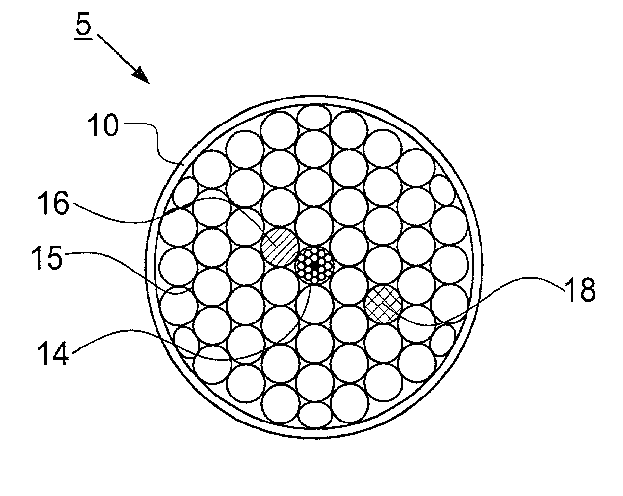
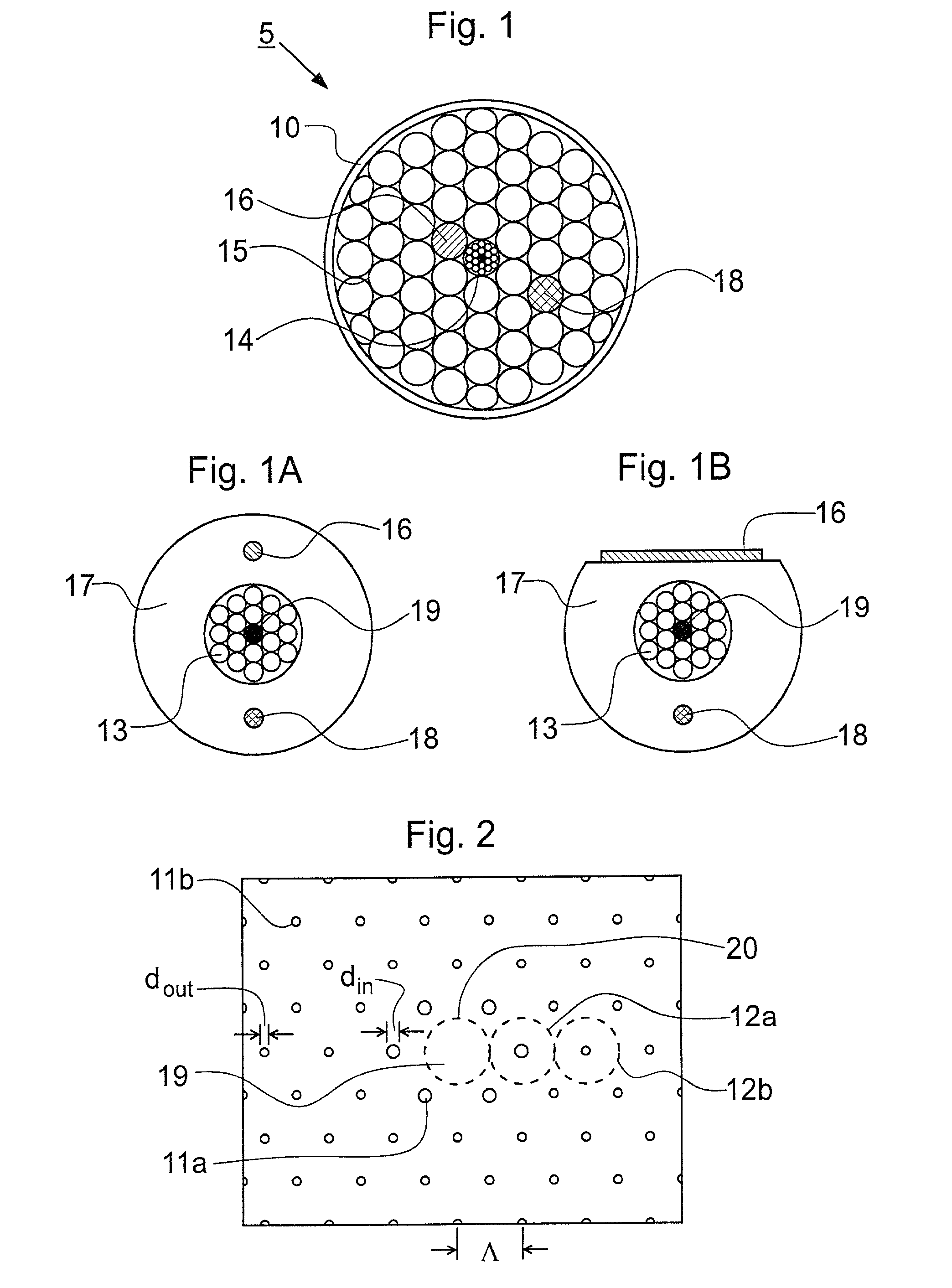
[0057] FIG. 1 is a sectional view of a holey fiber structure according to an embodiment of the invention. A microstructured inner cane 14 containing the optically active waveguiding part of the structure is supported by an array of larger-scale capillaries 15. The inner cane 14 comprises a solid core and a holey cladding, which are illustrated in more detail in FIG. 2, discussed further below. The support capillaries 15 are retained in a relatively thin outer jacket 10. In an alternative embodiment, the outer jacket could be dispensed with and the support capillaries fused together at the top and bottom prior to pulling. As can be seen from the figure, the support capillaries 15 have an outside diameter approximately the same as the outside diameter of the inner cane 14, so that the inner cane can be arranged with the support capillaries 15 in a hexagonal close packed array. More generally, it is convenient for the support capillaries to be of the same order of magnitude of lateral ...


PUM

PropertyMeasurementUnit
lengthaaaaaaaaaa
areaaaaaaaaaaa
areaaaaaaaaaaa

Abstract

An optical parametric device for broadband parametric processes involving first and second frequencies .omega..sub.1 and .omega..sub.2. The device comprises an optical fiber comprising a core and a cladding, the cladding being microstructured with holes for providing waveguiding confinement of at least one optical mode in the core. The optical fiber is poled lengthwise with a non-linearity profile having a period that satisfies a quasi phase matching (QPM) condition including the first and second frequencies. Through the use of a poled holey fiber of suitable hole structure, it is possible to increase the second harmonic (SH) efficiency in comparison with poled conventional (non-holey) fiber. This is achieved by a combination of a low mode overlap area between the fundamental and SH waves, a low absolute value of the mode area, and a large SH bandwidth per unit length of the fiber, all of which can be provided together in a poled holey fiber.

Description

BACKGROUND OF THE INVENTION[0001] The invention relates to optical devices based on parametric processes in non-linear waveguides.[0002] In a non-linear process involving multiple interacting fields of different frequencies, the phase velocities at the different frequencies will usually differ. As a result there will be no significant net energy transfer between the different interacting fields unless measures are taken to provide overall phase matching. Phase matching requires that the relative phase mismatch between the interacting fields is zero over the length of the optical path. Phase matching can be achieved in several ways, of which so-called quasi phase matching (QPM) is one widely used technique [1].[0003] QPM is based on the idea of providing a periodic modulation of the non-linear susceptibility .chi. along the optical path of a non-linear material, with the periodic modulation having a period .alpha. matched to the length over which two interacting fields develop a rela...

Claims


Application Information

Patent Timeline
Patent Type & Authority Applications(United States)
IPC IPC(8): G02B6/02G02F1/01G02F1/35G02F1/377G02F1/383G02F1/39
CPCG02B6/0208G02B6/02142G02B6/02214G02B6/02333G02B6/02338G02B6/02347G02B6/02357G02B6/0239G02F1/0115G02F1/3775G02F1/383G02F1/395G02F2001/3546G02F2202/07G02F2202/32G02F1/3546
Inventor BRODERICK, NEILPRUNERI, VALERIORICHARDSON, DAVIDMONRO, TANYA
Owner UNIV OF SOUTHAMPTON
Why Eureka
Try Eureka