Image display device

a display device and ground electrode technology, applied in the direction of cathode-ray/electron beam tube electrical connection, non-electron-emitting shielding screen, television system, etc., can solve the problems of low work efficiency, difficult removal of conductive silicone during recycle process, unstable electrical conduction, etc., and achieve high work efficiency

Inactive Publication Date: 2002-09-19
PANASONIC LIQUID CRYSTAL DISPLAY CO LTD +1
View PDF3 Cites 66 Cited by
  • Summary
  • Abstract
  • Description
  • Claims
  • Application Information

AI Technical Summary

Benefits of technology

0013] As described above, the construction in which the metal-foil grounding tape is used to provide connection between the conductive coat and the reinforcing band can realize a high work efficiency during its manufacturing process. However, in the case where the conductive coat

Problems solved by technology

However, in the case where the conductive coat has a multi-layer structure in which its outermost layer is an insulator, its electrical conduction becomes unstable.
However, the conductive silicone has the problems that its curing time after application is long and its handling until curing is not easy, and that its adhesion to the conductive coat after curing is good but the conductive silicone is difficult to remove during a recycle process and is inferior in work efficiency.
Furthermore, in the case of silicone having a high resistivity, in an antistatic film which includes a conductive coat having a surface resistance of several hundred .OMEGA./.quadrature. and is provided wit

Method used


Image

  • Image display device
  • Image display device
  • Image display device

Examples


first embodiment

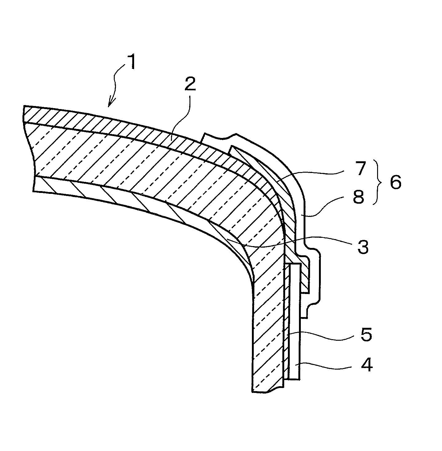
[0043] FIG. 1 is a cross-sectional view schematically illustrating the essential structure of a color cathode ray tube according to the invention. Reference numeral 1 denotes a panel of the color cathode ray tube, and a conductive coat 2 is formed on a surface of the panel 1. This conductive coat 2 is made of a multi-layer film having two or more layers. In this multi-layer film, a layer which is in contact with the panel 1 is an antistatic layer (conductive layer) containing metal particles or metal oxide particles. The outermost surface of the conductive coat 2 has an antireflection layer made of silica particles or a multi-layer interference film. The antireflection film on the outermost surface is an insulating layer whose index of refraction for light is low compared to the conductive layer and does not contain a conductive material such as metal particles or metal oxide particles. Reflection of external light on the screen of the color cathode ray tube is inhibited by the diff...

second embodiment

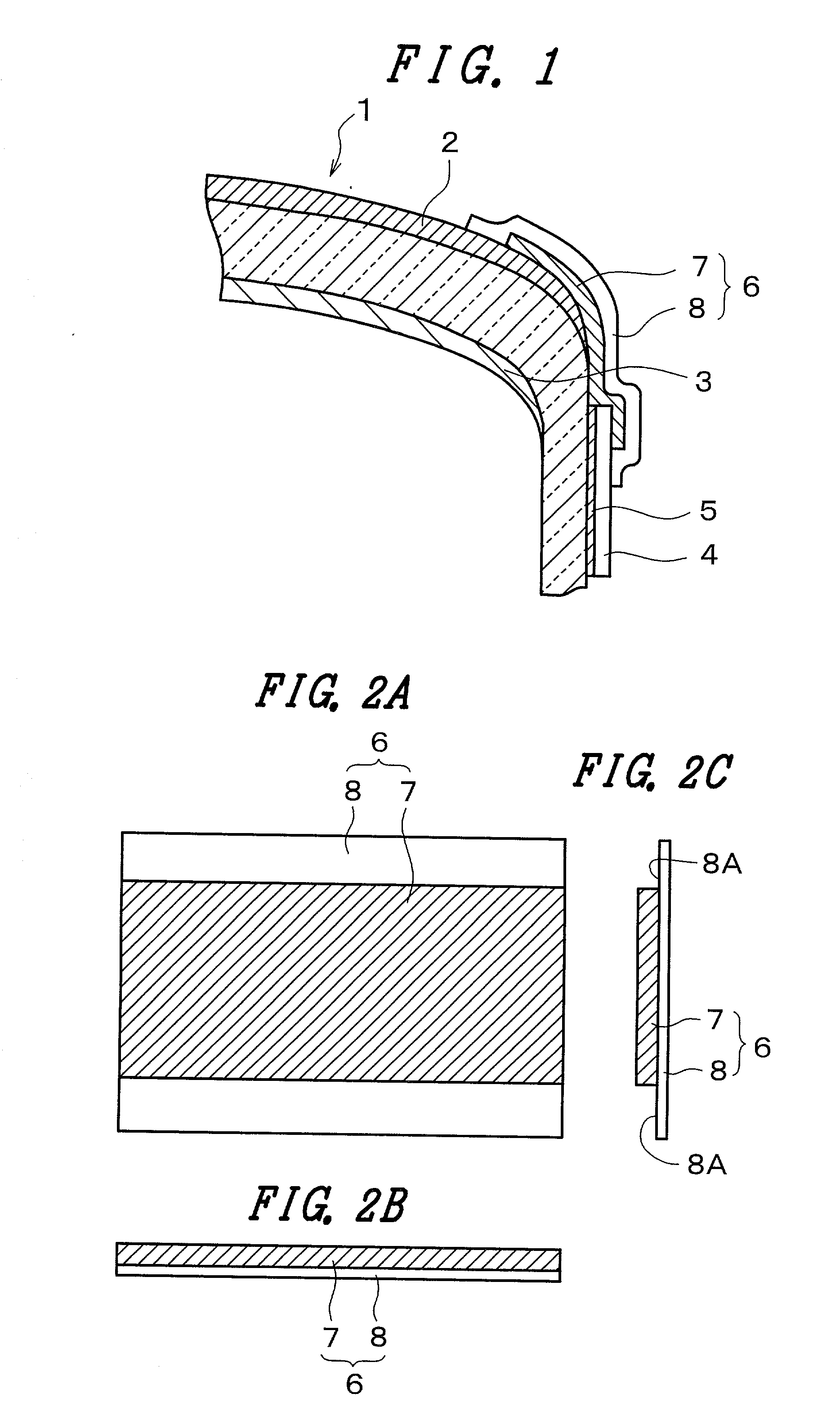
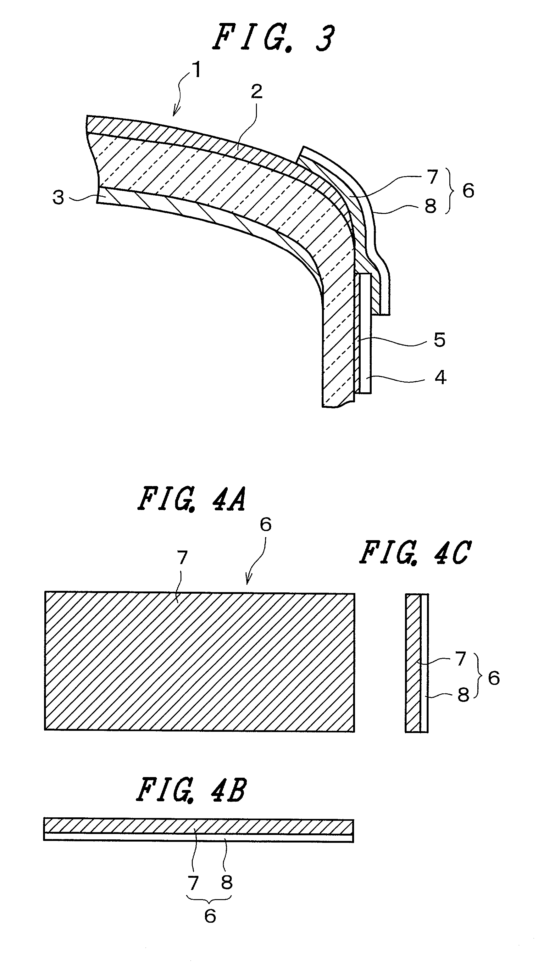
[0054] FIG. 3 is a cross-sectional view schematically illustrating the essential structure of a color cathode ray tube according to the invention. FIGS. 4A, 4B and 4C are explanatory views of the grounding electrode 6 shown in FIG. 3, and FIG. 4A is a plan view, FIG. 4B is a side view taken in a direction along its longer sides, and FIG. 4C is a side view taken in a direction along its shorter sides. In FIGS. 3 to 4C, the same reference numerals as those used in FIGS. 1 to 2C correspond to the same functional portions shown in FIGS. 1 to 2C. Incidentally, the direction along the short sides of the grounding electrode 6 is a direction which extends from the conductive coat 2 to the reinforcing band 4 as viewed in FIG. 3.

[0055] In the second embodiment, the insulating protective tape 8 which covers the back of the conductive adhesive material 7 described above in connection with the first embodiment is made the same in size as the conductive adhesive material 7 in planar directions (i...

third embodiment

[0056] FIG. 5 is a cross-sectional view schematically illustrating the essential structure of a color cathode ray tube according to the invention. FIG. 6 is a perspective view of the grounding electrode 6 shown in FIG. 5. In FIGS. 5 and 6, the same reference numerals as those used in FIGS. 1 to 4C correspond to the same functions portions shown in FIGS. 1 to 4C.

[0057] In the third embodiment, the grounding electrode 6 further includes a metal thin film 9 inserted between the insulating protective tape 8 and the conductive adhesive material 7 that are provided in the second embodiment. This metal thin film 9 is obtained by coating a resin film such as a PET film which constitutes the insulating protective tape 8 with an electrical good conductor such as aluminum, copper, chromium or silver by a vacuum evaporation process or a sputtering method.

[0058] The conductive adhesive material 7 is adhered to and stacked on the insulating protective tape 8 coated with the metal thin film 9, and...


PUM


Abstract

There is provided an image display device including a panel of good work efficiency which can prevent the destruction of its conductive coat due to discharge and can highly efficiently reduce the leakage of unwanted radiation electric fields. The image display device includes a panel grounding electrode which connects a conductive coat and a grounding member together, and the panel grounding electrode uses a conductive adhesive material having in the whole of an adhesive layer, and an insulative protective tape.

Description

BACKGROUND OF THE INVENTION[0001] The present invention relates to a panel grounding electrode and a display device, and more particularly, to a grounding electrode for providing electrical connection between a conductive coat and a grounding member such as a reinforcing band or a frame, the conductive coat having a low-reflection antistatic function or an unwanted radiation electric field leakage preventing function and being formed on a surface of a display area of a panel which constitutes an image display device such as a color cathode ray tube or a liquid crystal display panel, as well as to a display device which has an antistatic function or an unwanted radiation electric field leakage preventing function using such a grounding electrode.[0002] There are image display devices such as various kinds of cathode ray tubes including color cathode ray tubes and flat panel displays including liquid crystal panels and cold cathode panels. Such an image display device has a conductive...

Claims


Application Information

Patent Timeline
IPC IPC(8): H01J29/87H01J29/88H01J29/92
CPCH01J29/87H01J29/88
Inventor MATSUDATE, NORIHARUNAKAGAWA, ATSUO
Owner PANASONIC LIQUID CRYSTAL DISPLAY CO LTD
Why Eureka
Try Eureka