Optical diffusing plate, optical element and liquid crystal display

a technology of optical elements and optical diffusing plates, applied in the direction of polarising elements, identification means, instruments, etc., can solve the problems of chromatic light, difficulty in manufacturing, and inability to apply to a reflected type liquid crystal display

Inactive Publication Date: 2002-09-19
NITTO DENKO CORP
View PDF0 Cites 11 Cited by
  • Summary
  • Abstract
  • Description
  • Claims
  • Application Information

AI Technical Summary

Problems solved by technology

It is expected using this method that the following conventional problems may be solved; a problem based on a large wavelength dependability of a cholesteric liquid crystal in the conventional absorption loss reduction systems in which a cholesteric liquid crystal layer and a quarter wavelength plate are used, and especially, problems that transmitted light is chromatic from oblique direction and that these cannot be applied to a reflected type liquid crystal display etc.
However, in the above-mentioned conventional optical diffusing plate, there were problems of a difficulty in manufacturing, and of a practical usability in difficult handling with a poor functional stability, when applied in a liquid crystal display, etc.
Moreover, a possible chromatic problem based on high wavelength dependability as in cholesteric liquid crystal becomes rarely to be induced.

Method used


Image

  • Optical diffusing plate, optical element and liquid crystal display
  • Optical diffusing plate, optical element and liquid crystal display
  • Optical diffusing plate, optical element and liquid crystal display

Examples


example 1

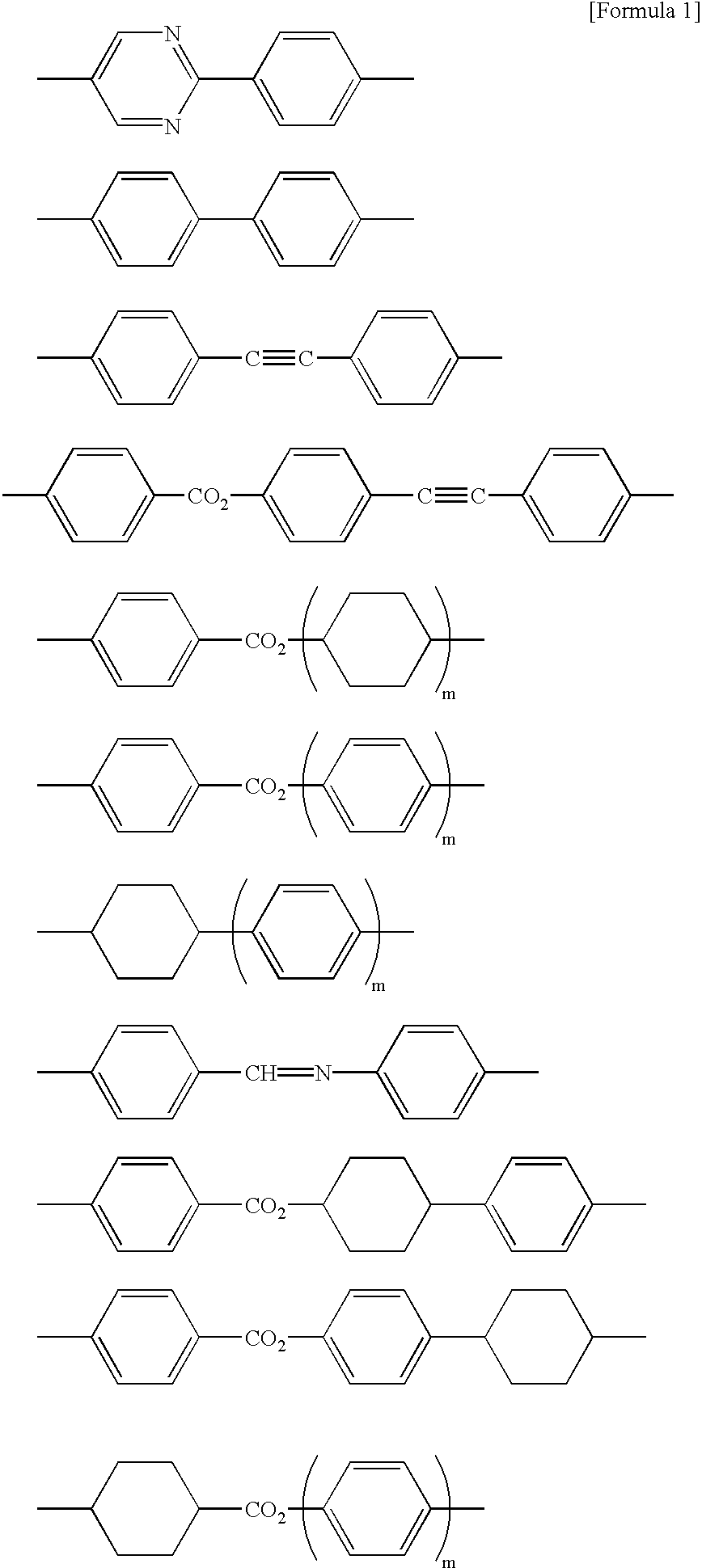
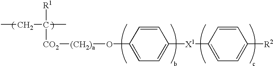
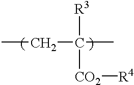
[0088] A 20 weight % solution in dichloro-methane containing a norbornene series resin (product by JSR Corporation, brand name ARTON) 100 parts as base material polymer of birefringent film and 6 parts of a side chain type liquid crystal polymer represented by the [Formula 5] (where n=35, represents molar % of monomer unit, and shown in block for convenience. Weight average molecular weight: 10500) are mixed together. The mixture was cast to form a film with a thickness of 100 .mu.m by a cast method. The film obtained was stretched at a stretching ratio of two at 175.degree. C. to obtain an optical diffusing plate comprising a birefringent film that contains a minute domain of the above-mentioned a side chain type liquid crystal polymer in dispersed state. 4

[0089] In the above-mentioned birefringent stretched film, a norbornene series resin forms a film, in which a side chain type liquid crystal polymer is dispersed having a shape of a domain in the form with a long axis in the stre...

example 2

[0093] Two birefringent films manufactured according to Example 1 were laminated and adhered together through acrylics series adhesive layer with thickness of 20 .mu.m so that the .DELTA.n2 directions of the films correspond to obtain an optical diffusing plate.

example 3

[0094] The optical diffusing plate obtained in Example 1, and a commercially available polarizing plate that has 41% of a total light transmittance and 99% of a polarization degree of transmission light was adhered together through an acrylics series adhesive layer so that the .DELTA.n2 direction corresponds with the transmission axis to obtain an optical element.


PUM

PropertyMeasurementUnit
transmittanceaaaaaaaaaa
refractive indexaaaaaaaaaa
lengthaaaaaaaaaa

Abstract

An optical diffusing plate that gives a anisotropic scattering of a linearly polarized light and has an excellent diffusion property in a scattering direction, and that is suitable for improving visibility, brightness of a liquid crystal display, comprising a birefringent film and a minute domain with a birefringent characteristic different from the birefringent film in a dispersed state in the birefringent film, the minute domain comprising a side chain type liquid crystal polymer comprising a monomer unit (a) containing a liquid crystalline fragment side chain and a monomer unit (b) containing a non-liquid crystalline fragment side chain, and a refractive index difference (DELTAn1) between the birefringent film and the minute domain in a direction orthogonal to a direction of axis that gives a maximum transmittance of linearly polarized light being 0.03 or more, and a refractive index difference (DELTAn2) in a direction of axis that gives a maximum transmittance being 80% or less of the DELTAn1.

Description

[0001] 1. Field of the Invention[0002] The present invention relates to an optical diffusing plate that gives an anisotropic scattering of a linearly polarized light and has an excellent diffusion property in a scattering direction, and that is suitable for improving visibility, brightness etc. of a liquid crystal display etc. Moreover, the present invention relates to an optical element using the optical diffusing plate concerned.[0003] 2. Description of the Prior Art[0004] Conventionally, an optical diffusing plate designed so that anisotropic scattering might be given to a linearly polarized light by making a domain with a refractive index anisotropy contained in a dispersed state in a base material has been known. As the optical diffusing plate concerned; an optical diffusing plate that comprises a combination of a thermoplastic resin and a low molecular weight liquid crystal, that comprises a combination of a low molecular weight liquid crystal and a photo-curable low molecular...

Claims


Application Information

Patent Timeline
Patent Type & Authority Applications(United States)
IPC IPC(8): B32B7/02C09K19/38G02B5/02G02B5/30G02F1/1335G09F9/00
CPCC09K19/3852G02B5/0236G02B5/0257G02B5/0278G02B5/3016G02F1/133528Y10T428/1036C09K2323/03G02F1/1335
Inventor NAKANISHI, SADAHIROMIYATAKE, MINORUNAKANO, SHUSAKUMOCHIZUKI, AMANE
Owner NITTO DENKO CORP
Why Eureka
Try Eureka