Synthetic silica glass optical member and method of manufacturing the same

a technology of optical components and silica glass, which is applied in the direction of glass making apparatus, glass deposition burners, manufacturing tools, etc., can solve the problems of reducing the image-focusing characteristics of lenses, insufficient luminance of wafers illuminated by optical systems, and insufficient silica glass

Inactive Publication Date: 2002-10-10
NIKON CORP
View PDF0 Cites 28 Cited by
  • Summary
  • Abstract
  • Description
  • Claims
  • Application Information

AI Technical Summary

Problems solved by technology

Since multiple lenses are typically combined in the optical system of the stepper, even if the decrease in the transmissivity in each lens is small, the cumulative effect of the transmission loss in the multiple lenses may result in insufficient luminance on a wafer illuminated by the optical system.
Also, as the wavelength of light becomes shorter, even a small fluctuation in refractive index within a lens may degrade the image-focusing characteristics of the lens.
Commercially available synthetic silica glass, however, does not satisfy such stringent requirements, particularly with regards to the homogeneity and the durability against ultra-violet rays, and therefore cannot be used in the precision optical instruments described above.
This conventional technique, however, does not pay any attention to residual carbon which may be included in the resultant glass through the u...

Method used


Image

  • Synthetic silica glass optical member and method of manufacturing the same
  • Synthetic silica glass optical member and method of manufacturing the same
  • Synthetic silica glass optical member and method of manufacturing the same

Examples


examples 1-1 to 1-6 , 2-1 to 2-4 , 3-1 to 3-3

Examples 1-1 to 1-6, 2-1 to 2-4, 3-1 to 3-3, and 4-1

[0056] Various examples of the silica glass of the present invention were manufactured. The silica glasses were evaluated in terms of their respective impurity concentrations. Specifically, the fluorine concentrations and carbon concentrations were measured by ion-chromatography using a combustion method. The Na concentrations were measured by activation analysis.

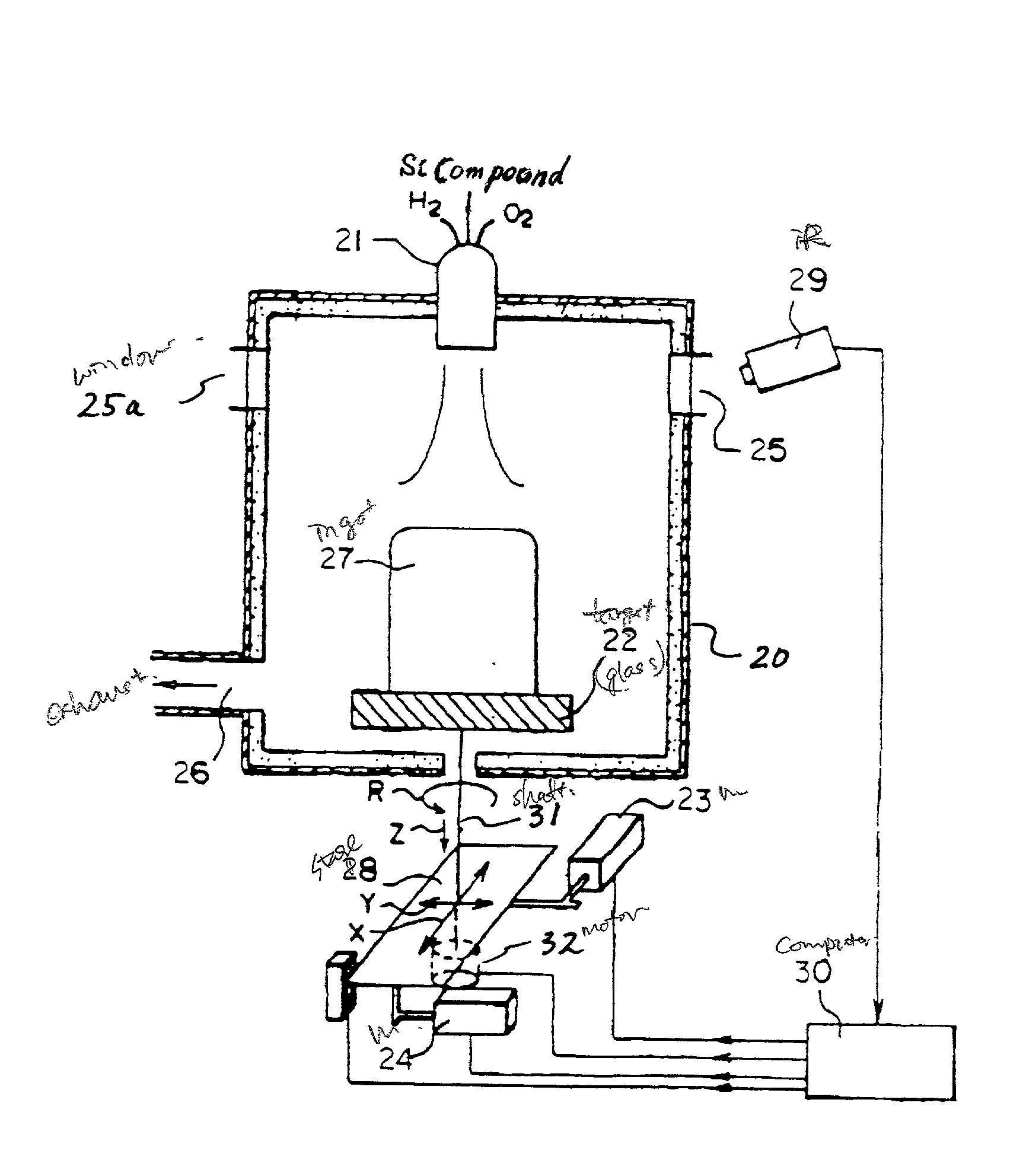
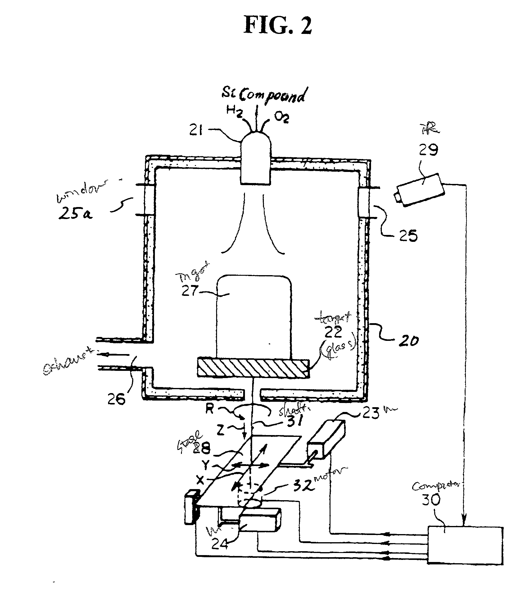
[0057] High-purity silica glass ingots were manufactured using a silica glass burner having a five-layered-pipe structure. Hydrogen gas and oxygen gas were emitted from the burner at the respective flow rates and flow speeds shown in Table 1 below and were reacted. Material gases (organic silicon compound and halogen compound) were diluted by a carrier gas and were emitted through the center of the burner together with the carrier gas. This method is generally categorized as the "oxy-hydrogen flame hydrolysis method."

[0058] FIG. 2 is a cross-sectional view of an apparatus ...

examples 5-1 to 5-5 , 6-1 to 6-4 , 7-1

Examples 5-1 to 5-5, 6-1 to 6-4, 7-1, and 7-2 (Introduction of Hydrogen)

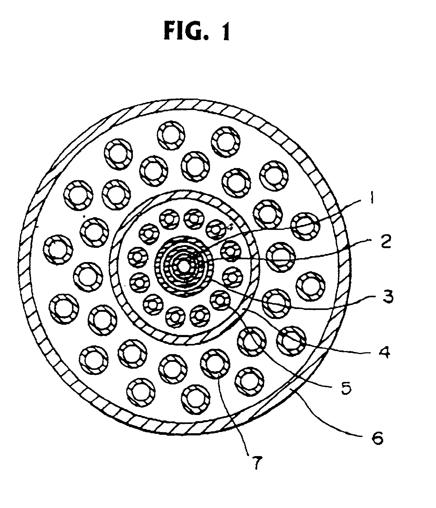
[0063] Various samples were manufactured employing the burner of FIG. 1 in the apparatus of FIG. 2. Manufacturing parameters are listed in Table 3 below. The resulting samples were evaluated in terms of the concentration of the OH group and the concentration of hydrogen molecules. The OH group concentrations were detected through infrared absorption at 2.7 .mu.m. The hydrogen molecule concentrations were detected using Raman spectroscopy according to the technique disclosed in V. S. Khotimchemko et al., Zhurnal Prikladnoi Spektroskopii, Vol. 46, No. 6, pp. 987-991, June 1987.

[0064] High-purity silica glass ingots were manufactured using a silica glass burner having the multi-pipe structure of FIG. 1. Hydrogen gas and oxygen gas were emitted from the burner 21 of the furnace 20 at the respective flow rates and flow speeds shown in Table 3 below and burned. High purity silicon tetrachloride (for samples 5-1 to 5-5...


PUM

PropertyMeasurementUnit
Fractionaaaaaaaaaa
Fractionaaaaaaaaaa
Fractionaaaaaaaaaa

Abstract

A method is provided for manufacturing a synthetic silica glass. The method includes the steps of emitting an oxygen containing gas and a hydrogen containing gas from a burner; emitting a mixture of an organic silicon compound and a halogen compound from the burner; and reacting the mixture with the oxygen containing gas and the hydrogen containing gas to synthesize the silica glass.

Description

[0001] This application claims the benefit of Japanese Applications No. 09-124529, filed in Japan on May 14, 1997, and No. 09-124530, filed in Japan on May 14, 1997, both of which are hereby incorporated by reference.[0002] 1 Field of the Invention[0003] The present invention relates to a method of manufacturing silica glass, and more particularly, to synthetic silica glass suited to optical members for use with ultra-violet lasers and a method of manufacturing the same.[0004] 2 Discussion of the Related Art[0005] An exposure apparatus called "stepper" has been used in conventional photolithography processes for projecting and exposing fine patterns of integrated circuits onto a silicon wafer or the like. In response to a recent demand towards higher integration of LSI chips, the wavelength of the light source used in such an exposure apparatus has been reduced from the g-line (436 nm) to the i-line (365 nm), and further, to KrF excimer lasers (248 nm) and to ArF excimer lasers (193...

Claims


Application Information

Patent Timeline
IPC IPC(8): C03B19/14
CPCC03B19/1415C03C2203/52C03B19/1453C03B2201/07C03B2201/12C03B2201/21C03B2201/23C03B2207/06C03B2207/12C03B2207/20C03B2207/22C03B2207/24C03B2207/32C03B2207/36C03C3/06C03C4/0071C03C4/0085C03C2201/12C03C2201/21C03C2201/23C03C2201/26C03C2201/50C03B19/1423C03B37/012C03B37/01807C03B37/01846Y02P40/57
Inventor FUJIWARA, SEISHINAKAGAWA, KAZUHIROJINBO, HIROKIKOMINE, NORIO
Owner NIKON CORP
Why Eureka
Try Eureka