Method of controlling an electrochemical machining process

a technology of electrochemical machining and control method, which is applied in the direction of machining electric circuits, manufacturing tools, instruments, etc., can solve the problems of non-conducting electrolyte regions, damage to electrodes and workpieces, and degrade the normal machining operation, so as to improve the surface quality of workpieces, improve machining accuracy, and reduce gap

Inactive Publication Date: 2002-11-14
KONINKLIJKE PHILIPS ELECTRONICS NV +1
View PDF6 Cites 28 Cited by
  • Summary
  • Abstract
  • Description
  • Claims
  • Application Information

AI Technical Summary

Benefits of technology

0034] A further advantageous embodiment is obtained by applying in the workpiece final shaping step, a sequence of intermittently applied current according to the method of claim 31. This extends the ability to improve either the machining accuracy by allowing a smaller gap or either the ability to improve the surface quality of the workpiece, both without reaching undesired process conditions.
0035] A next advantageous embodiment is obtained b

Problems solved by technology

However, in practice unwanted process conditions may arise that may degrade the normal machining operation.
Such spark discharges may give rise to damages to the electrode and the workpiece.
Another undesired process condition is the presence of gas-filled bubbles or cavities within the machining gap, causing non-conducting region

Method used


Image

  • Method of controlling an electrochemical machining process
  • Method of controlling an electrochemical machining process
  • Method of controlling an electrochemical machining process

Examples


Embodiment Construction

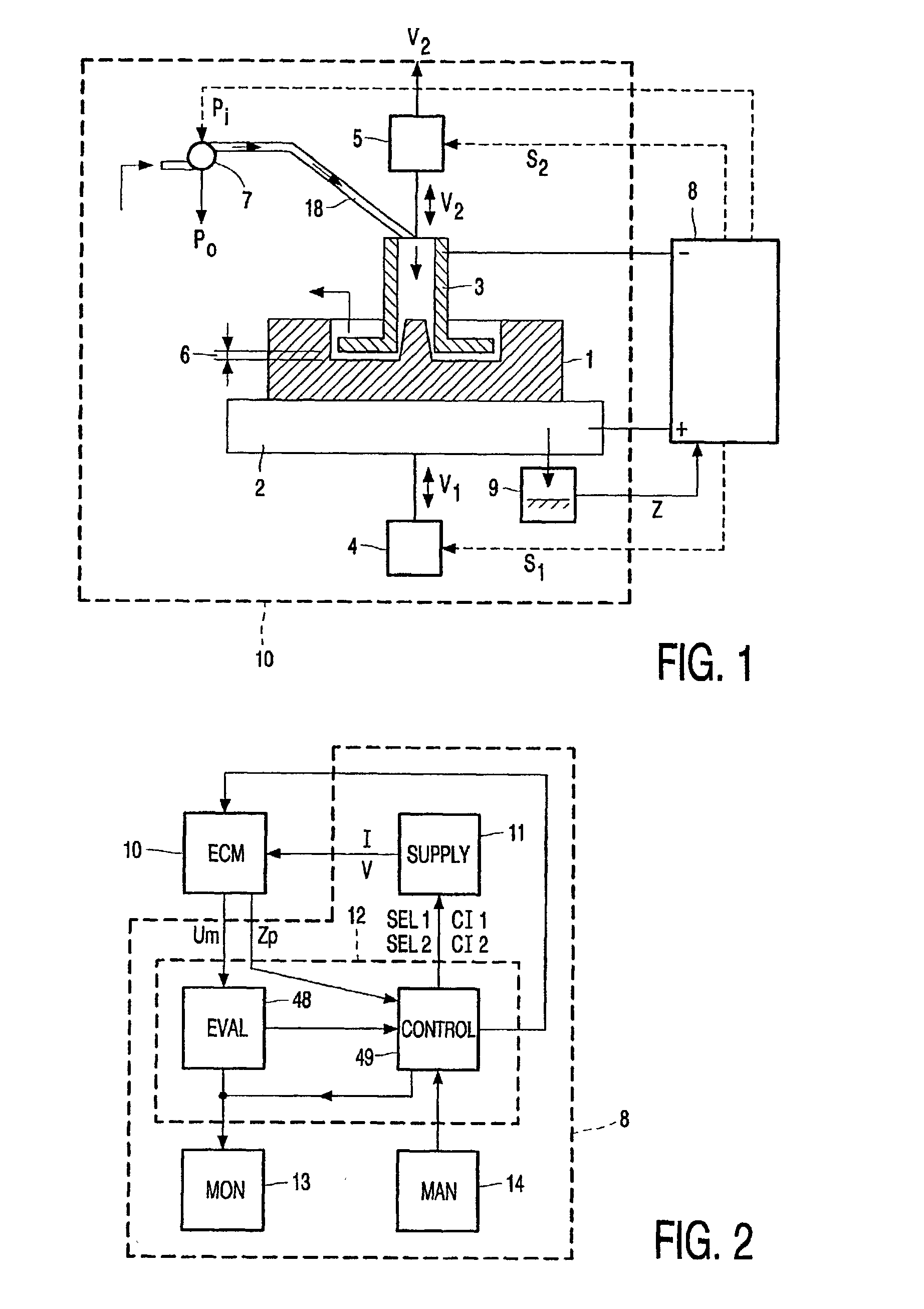
[0058] FIG. 1 illustrates schematically an arrangement for electrochemically machining a workpiece 1. The workpiece 1 is carried by a table 2 which moves with a feed rate V1, by means of first positioning means 4, towards an electrode tool 3. The workpiece 1, the electrode tool 3 and the table 2 are electrically conductive. The electrode tool 3 may be moved relative to the workpiece 1 with an electrode feed rate V2 by means of second positioning means 5. The second positioning means 5 may cause the electrode tool 3 to perform an oscillatory movement such as a harmonic movement or a non-harmonic repeated movement relative to the workpiece 1. This may be realized by means of, for example a crank shaft which is driven by a motor or by hydraulic means. The first positioning means 4 may comprise linear displacement means comprising a threaded shaft. The first positioning means 4 are controlled by a first positioning control signal S1 while the second positioning means 5 are controlled by...


PUM

PropertyMeasurementUnit
Timeaaaaaaaaaa
Timeaaaaaaaaaa
Timeaaaaaaaaaa

Abstract

A method of controlling a process of electrochemically machining an electrically conductive workpiece employing the spectral composition of the measured voltage within a predetermined measuring period such as induced by an applied current between the electrically conductive workpiece and an electrode tool. A process of electrochemically machining employing a material removing step with electric current supplied continuously and an a workpiece shaping step with electric current supplied intermittently. An advantageous embodiment employs extreme short pulses.

Description

[0001] The invention relates to a method of controlling a process of electrochemically machining an electrically conductive workpiece as recited in the preamble of claim 1 as well as to a method of electrochemically machining as recited in the preamble of claim 30. The invention further relates to an arrangement for a performing a method of controlling a process of electrochemically machining as recited in the preamble of claim 39 as well as to an arrangement of electrochemically machining as recited in the preamble of claim 68.[0002] Electrochemically machining is a process in which an electrically conductive workpiece is dissolved at the location of an electrode while electrolyte and electric current is supplied. For this purpose, the electrode is brought in proximity of the workpiece and, while electrolyte is fed into the gap between the workpiece and the electrode, a current is passed through the workpiece and the electrode via the electrolyte, the workpiece being positive with ...

Claims


Application Information

Patent Timeline
IPC IPC(8): B23H3/02B23H7/30
CPCB23H2300/10B23H3/02B23H2300/12
Inventor BRUSSEE, MAARTENGIMAEV, NASICH Z.ZAJCEV, ALEKSANDR N.BELOGORSKIJ, ALEKSANDR L.AGAFONOV, IGOR L.ZHITNIKOV, VLADIMIR PAVLOVICHKUCENKO, VIKTOR N.MUCHUTDINOV, RAFAIL R.
Owner KONINKLIJKE PHILIPS ELECTRONICS NV
Why Eureka
Try Eureka